Download
1 / 29
341 likes | 708 Views
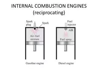
Combustion engines main principles and definitions Reciprocating combustion engines architecture Reciprocating engines dynamic properties Engine components and systems The engine management system for gasoline and Diesel engines The emission Requirements & Technology

E N D
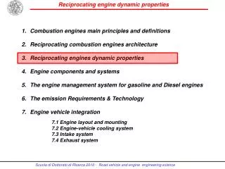
Combustionenginesmainprinciples and definitions Reciprocating combustionengines architecture Reciprocating engines dynamic properties Engine components and systems The engine management system for gasoline and Diesel engines The emission Requirements & Technology Engine vehicle integration 7.1 Engine layout and mounting 7.2 Engine-vehicle cooling system 7.3 Intake system 7.4 Exhaust system
Reciprocating engines dynamic properties Engine operation forces Engine Excitation Mechanisms (Single Cylinder Engine) Key issue on masses balancing • In line 4 cylinder engine balance • Flat 4 cylinder engine balance • In line 5 cylinder engine balance • In line 6 cylinder engine balance • V60° 6 cylinder engine balance • V90°- 30°crank offset 6 cylinder engine balance • V90° 8 cylinder engine balance • V90° - flat crankshaft 8 cylinder engine balance • John Heywood, Internal Combustion Engine Fundamentals / McGraw-Hill • Charles F. Taylor, The internal Combustion Engine in Theory and Practice /The M.I.T. Press • Automotive Handbook – R. Bosch/SAE • Advanced engine technology (Heinz Heisler) – Butterworth/Heinemann • Light and Heavy Vehicle Technology (M.J. Nunney) - CGIA, MSAE, MIMI
Engine operation forces • The purpose of the piston-connecting rod-crankshaft assembly in the reciprocating piston-engines is to transform the gas forces generated during combustion within the working cylinder into a piston stroke, which the crankshafts converts into useful torque available at the flywheel. The cyclic operation leads to unequal gas forces, and the acceleration and deceleration of the reciprocating power-transfer components generate inertia forces. • The mass inertia properties of the piston-connecting rod-crankshaft assembly are a composite of the rotating mass of the crankshaft about their axis and the reciprocating masses in the cylinder direction. • The inertial properties of a single cylinder engine are determined by the piston mass, exclusively oscillating mass, the crankshaft mass, exclusively rotating mass, and the corresponding connecting-rod mass components, usually assumed to amount to 1/3 for rotating and to 2/3 for oscillating mass. • The inertia force components are identified as inertial forces of the 1st, 2nd, 4th order, depending upon their rotational frequencies, relative to engine speed: in general only the 1st and 2nd-order components are significant. • In the case of multi-cylinder engines, free moments of inertia are present when all the complete crankshaft assembly’s inertial forces combine to generate a force couple at the crankshaft.
Eccitanti alterne di inerzia in un motore alternativo monocilindro Eccitanti alterne di inerzia in un motore alternativo monocilindro Massa w = q + l q alterna m 2 acc r * * [cos cos( 2 )] a w = q d / dt = = + Force m * acc F F a I II The alternate motion of the con rod - crank system Il Motore come sorgente di vibrazioni e rumore Fig. 1. 1 Inertia or mass forces
Considerations on gas forces • The gas forces are generated by the fuel combustion acting on the piston to be transferred to the crankshaft by connecting- rod through the expansion stroke: therefore during the complete cycle they depend on the crankshaft position. • When multiplied by the crank radius, the gas forces produce a periodically variable torque value. • The diagram shows the curve of the engine torque as a function of crankshaft position: this is one of the most important characteristics in assessing the dynamic engine behavior.
Considerations on gas forces • In multiple cylinder engines, the torque curve of the individual cylinders are superimposed with a phase shift dependent on the numbers of cylinders, their configuration, crankshaft design and firing sequence. The resulting composite curve is characteristics of the engine design and covers a full working cycle. • Harmonic analysis can lead to a “torsional harmonics” by a series of sinusoidal oscillations featuring whole-number multiples of the basic frequencies. • The cyclic torque fluctuation leads to a variations of the crankshaft’s rotation speed, called cyclic variation and defined as: • Energy storage devices, as the flywheel and the clutch spring, must be design to adequately compensate for the variations of rotation speed in normal applications.
Engine Orders • Engine orders are simply the amplitudes of the frequency components which are the multiples of the rotating frequency. Engine orders, which are determined by an order analysis are extensively used in the vibration and noise work to identify the source of excitation (order) and, hence, its frequency of an engine induced problem. For example, a four cylinder in-line engine will always has its second order component as the dominant excitation. • 2E • In four-cylinder four-stroke engines this notation is often used to denote an engine order where the frequency is two times the engine rotational speed. • 3E • Basic firing frequency of a six-cylinder four-stroke engine. • 4E • Two times engine firing frequency of a four-cylinder four-stroke engine. It is the basic firing frequency of an eight-cylinder four-stroke engine. Engine order meaning
Engine Excitation Mechanisms (Single Cylinder Engine) 1/5 Inertia Force - The displacement of the piston with respect to crank angle can be derived from simple trigonometry. This can then be differentiated to yield velocity and acceleration of the piston. The expressions obtained tend to be very complicated and can be simplified into the expression containing only first order (once per revolution), second order (twice per revolution), and a negligible fourth order. Note: if R/L<0.3 it is accurate enough to use just the first two terms. Inertia force is obtained by multiplying the piston acceleration by the reciprocating mass and acts only in the line of the cylinders.
Engine Excitation Mechanisms (Single Cylinder Engine) 2/5 Gas Forcing The rate of rise and peak cylinder pressure of the diesel (13MPa at approximately 20° after TDC) are approximately twice that of the gasoline with the angle the peak occurs at typically 5° earlier. Diesel and gasoline combustion is random even at full load, worse at part load and particularly poor at idle. Therefore, it is normal to talk about the average peak cylinder pressure (Pmax mean) and standard deviation of Pmax. This variability both cycle to cycle and cylinder to cylinder is one source of half order excitation. Equilibrium of Forces The gas force that acts on the piston also acts on the cylinder head. The force on the piston splits into two components, one acting down the rod and one acting sideways on the cylinder wall. The forces are reacted at the main bearing but a couple exists between the horizontal reaction at the bearing and the piston side force. This couple is equal to the crankshaft output torque, so the crankshaft torque is reacted by forces on the engine structure. The gas force components of the vertical force at the bearing is equal and opposite to the force acting on the cylinder head, but of course the inertia component is unbalanced.
Torsional Excitation of Crankshaft and Engine Structure - The total torque acting on the crankshaft of the single cylinder engine results from the effect of the gas and inertia forces on the crank slider mechanism.The torque resulting from piston motion is often called the INERTIA torque and is represented by the equation: • where • ti = Inertia torque [Nm] • Torque resulting from piston motion alone for a single cylinder engine. Engine Excitation Mechanisms (Single Cylinder Engine) 3/5
The torque resulting from gas pressure alone is represented by the equation: • where • tg = Gas torque [Nm] • Pg = Gas pressure [Nm-2] • A = Area of top of piston [m-2] • Torque resulting from gas pressure alone for a single cylinder engine. Engine Excitation Mechanisms (Single Cylinder Engine) 4/5
The total torque is found by summing these two components. • Note that the torque from gas pressure dominates (for the engine firing case). The sum of the inertia and the gas torques is present at the flywheel and has to be reacted by the engine structure Engine Excitation Mechanisms (Single Cylinder Engine) 5/5 • Total torque for a single cylinder engine
Simplified understanding of Primary and Secondary inertia forces Primary inertia forces.These arise from the force that mustbe applied to accelerate the piston over the first half of itsstroke, and similarly from the force developed by the pistonas it decelerates over the second half of its stroke. When the piston is around the mid-stroke position itis then moving at the same speed as the crankpin and noinertia force is being generated.For an engine to be acceptable in practice, the arrangementand number of its cylinders must be so contrived that the primaryinertia forces generated in any particular cylinder aredirectly opposed by those of another cylinder. Where the primaryinertia forces cancel one another out in this manner,as for example in an in-line or a horizontally opposed four-cylinderengine with the outer and inner pair of pistons movingin opposite directions, the engine is said to be in primarybalance. Secondary inertia forces.These are due to the angular variationsthat occur between the connecting rod and the cylinderaxis as the piston performs each stroke. As a consequence ofthis departure from straight-line motion of the connectingrod, the piston is caused to move more rapidly over the outer half of its stroke than it does over the inner half. That is, thepiston travel at the two ends of the stroke differs for the sameangular movements of the crankshaft. Theresulting inequality of piston accelerations and decelerationsproduces corresponding differences in the inertia forces generated.Where these differing inertia forces can be both matchedand opposed in direction between one cylinder and another, asfor example in a horizontally opposed four-cylinder enginewith corresponding pistons in each bank moving over identicalparts of their stroke the engine is said tobe in secondary balance.It is not always practicable for the cylinders to be arrangedso that secondary balance can be obtained, but fortunatelythe vibration effects resulting from this type of imbalance aremuch less severe than those associated with primary imbalanceand can usually be minimized by the flexible mountingsystem of the engine. This is confirmed by the long-establishedand popular in-line four-cylinder engine, which possessesprimary balance but lacks secondary balance. However, thecontinuing search for greater refinement of running with thistype of engine led, in the mid 1970s, to a revival of interestin the use of twin counterbalancing shafts for cancelling outthese secondary inertia forces. (http://www.epi-eng.com/piston_engine_technology/piston_motion_basics.htm)
Key issue on masses balancing • Some measures are employed to get partial or complete compensation of the forces and moments of inertia generated from the crankshaft assembly. • All masses are externally balanced when no free inertial forces or moments are transmitted to the outside through the cylinder block. However, the remaining internal forces and moments apply various loads and deformative-vibratory stresses to the engine mounts and block. • The simplest way to balance rotating mass is to use counterweights to generate an equal force to oppose the centrifugal one. • The 1-st order inertial forces are propagated at crankshaft speed, while the periodicity of the 2nd-order forces is twice the crankshaft's rotational rate. These forces are compensated by a counterweight balance system designed for opposed rotation at a rate equal to or twice that of the crankshaft. The balance forces’ magnitudes must equal those of the rotating inertial force vectors acting in the opposite direction. • In multiple cylinder engine, the mutual counteractions of the various components in the crankshaft assembly are one of the key factor determining the crankshaft configuration and consequently the engine design. The inertial forces are balanced if the common center of gravity for all moving components lies at the crankshaft midpoints: i.e. if the crankshaft is symmetrical.
Firing sequence • The firing sequence is the sequence in which combustion is initiated in the cylinders. • The arrangement of the crankthrows is determined by the requirements for even firing intervals of the cylinders and for spacing the successive power impulses as far apart as possible along the crankshaft, so as to reduce torsional deflections or twisting effects. For any four-stroke engine the firing intervals must, if they are to be even, be equal to 720° divided by the number of cylinders. • The firing sequences determines the position of the crankthrows and is defined considering: • engine design configuration • uniformity of ignition intervals • ease of crankshaft manufacture • minimization of crankcase load patterns
1-st and 2-nd order free forces and moments for the most common engine configurations
1-st and 2-nd order free forces and moments for the most common engine configurations
2Cil 3Cil 4Cil 8Cil Optimum cylinder number vs engine displacement 500 1000 1500 2000 2500 3000 3500 4000 5Cil 6Cil
In line 4 cylinder engine The Inline-four engine or Straight-four engine is an internal combustion engine with all four cylinders mounted in a straight line, or plane along the crankcase. For in-line four-cylinder engines the first and fourth crankthrows are therefore indexed on one side of the crankshaft and the second and third throws on the other side. The firing order of these engines, numbering from the front, may then be either 1-3-4-2 or 1-2-4-3 at 180° intervals. The inline-four is not a fully balanced configuration. An even-firing inline-four engine is in primary balance because the pistons are moving in pairs, and one pair of pistons is always moving up at the same time as the other pair is moving down. However, piston acceleration and deceleration are greater in the top half of the crankshaft rotation than in the bottom half, because the connecting rods are not infinitely long, resulting in a non sinusoidal motion. As a result, two pistons are always accelerating faster in one direction, while the other two are accelerating more slowly in the other direction, which leads to a secondary dynamic imbalance that causes an up-and-down vibration at twice crankshaft speed. This imbalance is tolerable in a small, low-displacement, low-power configuration, where alternate weight and stroke are moderate, but the vibrations get worse with increasing size and power. Above 2.0 L, most modern inline-four engines now use balance shafts to eliminate the second-order harmonic vibrations. In a system invented by Dr. Frederick W. Lanchester in 1911, and popularized by Mitsubishi Motors in the 1970s, an inline-four engine uses two balance shafts, rotating in opposite directions at twice the crankshaft's speed, to offset the differences in piston speed.
Flat 4 cylinder engine (boxer) A flat-4 or horizontally-opposed-4 is a flat engine with four cylinders arranged horizontally in two banks of two cylinders on each side of a central crankcase. The pistons are usually mounted on the crankshaft such that opposing pistons move back and forth in opposite directions at the same time, somewhat like a boxing competitor punching their gloves together before a fight, which has led to it being referred to as a boxer engine. However, the flat-4 does have a less serious secondary imbalance that causes it to rotate back and forth around a vertical axis twice per crankshaft revolution (2nd order free moment). This is because the cylinders cannot be directly opposed, but must be offset somewhat so the piston connecting rods can be on separate crank pins, which results in the forces being slightly off-centre. The vibration is usually not serious enough to require balance shafts. The configuration is characterized by a low centre of gravity, and a very short engine length, however the two overheads imply a higher production cost and a higher complexity of the intake and exhaust system layout; generally the ground clearance of the bottom side can be a problem.
SUBARU New Diesel boxer engine
Inline 5-cylinder engine The straight-five engine or inline-five engine is an internal combustion engine with five cylinders aligned in one row or plane, sharing a single engine block and crankcase. A five-cylinder engine gets a power stroke every 144 degrees (720° ÷ 5 = 144°). Since each power stroke lasts 180 degrees, this means that a power stroke is always in effect. Because of uneven levels of torque during the expansion strokes divided among the five cylinders, there is increased secondary-order vibrations. At higher engine speeds, there is an uneven third-order vibration from the crankshaft which occurs every 144 degrees. Because the power strokes have some overlap, a five-cylinder engine may run more smoothly than a non-overlapping four-cylinder engine, but only at limited mid-range speeds where second and third-order vibrations are lower. In conclusion the main disadvantage is that a straight-five design has free moments (vibrations) of the first and second order on the cylinder plane: the first one may be balanced by a balance shaft, rotating in opposite directions at the crankshaft's speed, and by proper weight (rotational component) on the crankshaft itself. Firing order can be 1-2-4-5-3 or 1-5-4-3-2:with the last one the 2° order free moment is lower while higher the first one.
Inline 6 cylinder engine The straight-six engineor inline-six engineis a six cylinder internal combustion engine with all six cylinders mounted in a straight line along the crankcase. The single bank of cylinders may be oriented in either a vertical or an inclined plane with all the pistons driving a common crankshaft. The crankthrows are spaced in pairs with an angle of 120° between them: hence, the first and sixth crankthrows are paired, as are the second and fifth, and likewise the third and fourth. The firing order may then be such that no two adjacent cylinders fire in succession; that is, either 1-5-3-6-2-4 or 1-4-2-6-3-5 at, of course, 120° intervals. An inline six engine is in perfect primary and secondary mechanical balance. The engine is in primary balance because the front and rear trio of cylinders are mirror images, and the pistons move in pairs; that is, piston #1 balances #6, #2 balances #5, and #3 balances #4, largely eliminating the polar rocking motion that would otherwise result. Secondary imbalance is avoided because an inline six cylinder crankshaft has six crank throws arranged in three planes offset at 120°. The result is that differences in piston speed at any given point in rotation are effectively canceled. Crankshafts on six cylinder engines generally have either four or seven main bearings: larger engines and diesels tend to use the latter because of high loadings and to avoid crankshaft flex. Many of the more sporty high-performance engines use the four bearing design because of better torsional stiffness (e.g., BMW small straight 6's, Ford's Zephyr 6). The accumulated length of main bearing journals gives a relatively torsionally flexible crankshaft. The four main bearing design has only six crank throws and four main journals, so is much stiffer in the torsional domain. At high engine speeds, the lack of torsional stiffness can make the seven main bearing design susceptible to torsional flex and potential breakage.
V60° - 6 cylinder engine A V6 engine is a V engine with six cylinders mounted on the crankcase in two banks of three cylinders, usually set at either a right angle or an acute angle to each other, with all six pistons driving a common crankshaft. Due to the odd number of cylinders in each bank, V6 designs are inherently unbalanced, regardless of their V-angle. All straight engines with an odd number of cylinders suffer from primary dynamic imbalance, which causes an end-to-end rocking motion. Each cylinder bank in a V6 has an odd number of pistons, so the V6 also suffers from the same problem unless steps are taken to mitigate it. In the horizontally-opposed flat-6 layout, the rocking motions of the two straight cylinder banks offset each other, while in the inline-6 layout, the two ends of engine are mirror images of each other and compensate every rocking motion. Concentrating on the first order rocking motion, the V6 can be assumed to consist of two separate straight-3 where counterweights on the crankshaft and a counter rotating balancer shaft compensate the first order rocking motion. At mating, the angle between the banks and the angle between the crankshafts can be varied so that the balancer shafts cancel each other 90° V6 (larger counter weights) and the even firing 60° V6 with 60° flying arms (smaller counter weights). The second order rocking motion can be balanced by a single co-rotating balancer shaft. The most efficient cylinder bank angle for a V6 is 60 degrees, minimizing size and vibration. While 60° V6 engines are not as well balanced as inline-6 and flat-6 engines, modern techniques for designing and mounting engines have largely disguised their vibrations. Unlike most other angles, 60 degree V6 engines can be made acceptably smooth without the need for balance shafts. When Lancia pioneered the 60° V6 in 1950, a 6-throw crankshaft was used to give equal firing intervals of 120°. However, more modern designs often use a 3-throw crankshaft with what are termed flying arms between the crankpins, which not only give the required 120° separation but also can be used for balancing purposes. Combined with a pair of heavy counterweights on the crankshaft ends, these can eliminate all but a modest secondary imbalance which can easily be damped out by the engine mounts. Two firing order are possible: 1-5-3-6-2-4 or 1-2-4-6-5-3.
V90° /30° offset - 6 cylinder engine The Buick V6 was notable because it introduced the concept of uneven firing, as a result of using the 90° V8 cylinder angle without adjusting the crankshaft design for the V6 configuration. Rather than firing every 120° of crankshaft rotation, the cylinders would fire alternately at 90° and 150°, resulting in strong harmonic vibrations at certain engine speeds. These engines were often referred to by mechanics as "shakers", due to the tendency of the engine to bounce around at idle speed. To overcome the problem of uneven firing intervals with a 90° V6 engine, Buick in America retained three-throw crankshaft but ingeniously replaced the common, double-length, crankpins by adjacent single crankpins that were staggered by 30° in opposite directions to produce a so-called ‘split-pin’ crankshaft. More modern 90° V6 engine designs avoid these vibration problems by using crankshafts with offset split crankpins and often by adding balancing shafts to balance the 1st order free moment. Examples include the later versions of the Buick V6, and earlier versions of the Mercedes-Benz V6 and AUDI V6. The Mercedes V6, although designed to be built on the same assembly lines as the V8, used split crankpins, a counter-rotating balancing shaft, and careful acoustic design to make it almost as smooth as the inline-6 it replaced. However, in later versions Mercedes changed to a 60° angle, making the engine more compact and allowing elimination of the balancing shaft. Despite the difference in V angles, the Mercedes 60° V6s were built on the same assembly lines as 90° V8s.
V90° /30° offset - 6 cylinder engine Balancing shaft to balance the 1st order free moment 30°Split crank pin AUDI – V6/90° Gas engine
V90° - 8 cylinder engine Share the same crank pin • There are two classic types of V8s which differ by crankshaft: • The cross-plane or two-plane crankshaft (crank pins at a 90° angle) is the configuration used in most V8 road cars. The first and last of the four crank pins are at 180° with respect to each other as are the second and third, with each pair at 90° to the other, so that viewed from the end the crankshaft forms a cross. The last cylinder is not in the same position as the first, so there is end-to-end vibration again, which can be solved by adding counterweights to the crankshaft which balance the forced created by the pistons This makes the cross-plane V8 a slow-revving engine that cannot speed up or slow down very quickly compared to other designs, because of the greater rotating mass. While the firing of the cross-plane V8 is regular overall, the firing of each bank is LRLLRLRR. In stock cars with dual exhausts, this results in the typical V8 burble sound that many people have come to associate with American V8s, In all-out racing cars it leads to the need to connect exhaust pipes between the two banks to design an optimal exhaust system, resulting in an exhaust system that resembles a bundle of snakes as in the Ford GT40. This complex and encumbering exhaust system has been a major problem for single-seater racing car designers, so they tend to use flat-plane crankshafts instead. • The flat-plane or single-plane crankshaft (crank pins at 180°) - In its simplest form, it is basically two straight-4 engines sharing a common crankshaft. When the engine runs, the pistons shoot up and down, the first and last pistons of the bank occupying matching positions on either end of the array, so that the force on both ends is equal and the system is balanced. However, this simple configuration, with a single-plane crankshaft, has the same secondary dynamic imbalance problems as two straight-4s, resulting in vibrations in large engine displacements. The induced vibrations can be eliminated by the use of balance shafts, with a counter rotating pair flanking the crankshaft to counter second order vibration transverse to the crankshaft centerline. As it does not require counterweights for the primary balance, the crankshaft has less mass and thus inertia, allowing higher rpm and quicker acceleration. The design was popularized in modern racing with the Coventry Climax 1.5 L (~92 cu in) V8 that evolved from a cross-plane to a flat-plane configuration. Flat-plane V8s on road cars come from Ferrari, (every V8 model they ever made, from the 1973 308 GT4, to today's F430 and California), Lotus (the Esprit V8 ), and TVR (the Speed Eight). This design is popular in racing engines, the most famous example being the Cosworth DFV.
V90° - 8 cylinder engine BMW– V8/90° Motorsport
V90° - 8 cylinder engine 20 8 cil V90°- Cross-plane crankshaft