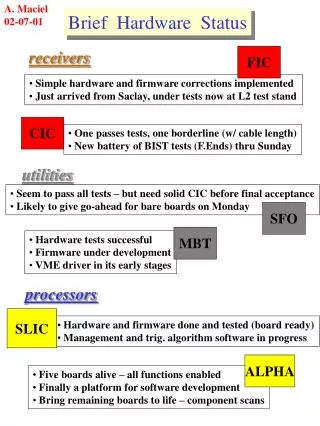
Data Processor Status Hardware
Data Processor Status Hardware. Giuseppe Osteria INFN Napoli. Giuseppe Osteria INFN Sezione di Napoli. Paris, October 12, 2012. Euso Balloon 8th progress meeting. OUTLINE. DP reminder DP external interfaces DP internal interfaces DP sub-assemblies status CPU & DST CLK board

Data Processor Status Hardware
E N D
Presentation Transcript
Data Processor StatusHardware Giuseppe Osteria INFN Napoli Giuseppe Osteria INFN Sezione di Napoli Paris, October 12, 2012 Euso Balloon 8th progress meeting
OUTLINE • DP reminder • DP external interfaces • DP internal interfaces • DP sub-assemblies status • CPU & DST • CLK board • GPS receiver • DP box • DP pre-integration test • DP Software Status & dev. plan
Data Processor subassembly items The DP functionality is obtained by connecting different specialized items, which form a complex system. The main subassembly items are: • Control Cluster Board (CCB) • Main processing unit (CPU) • Data Storage (DST) • Housekeeping system (HK) • Clock Board (CLKB) • GPS receiver (GPSR) • Data Processor Power Supplies (DP-LVPS1-2-3) • PDM Power Supply (PDM-LVPS)
Data Processor block diagram 28V DP LVPSs V, A Monitor Relays v 28V HL-CMD CC HK system SIREN system RS 422 12V RS422 CPU Ethernet V, T mon. SPI 5V Analog ( T) CCB v SpaceWire to PCI SpaceWire 12V, 5V v Analog (V, T) Data Storage Analog ( T) v SATA CLKs, Sync, Trig, Busy 5V CLK board v v PCI SpaceWire SPI Fast parallel link v RS232 1PPS PWP 5V GPS TLS Visible cam (adv. opt.) PDM box IR Camera (adv. opt.)
External interfaces • DP-SIREN • CPU-Siren data telemetry interface • Ethernet • HK-Siren command interface • RS422 (level adapter to RS232) • Open drain (switch ON/OFF)? • DP-TLS • HK-lenses/structure • Temperature sensors (analog) • heaters?, motors?, other? (TBD)
External interfaces • DP- PDM • CCB-PDM-board data/cmd interface (OK!) • Parallel data link (40 MHz, 8 bit) PDMCCB • SPI (2 MHz) for commands CCBPDM • Clock/Control signals • Broadcast signal (external trigger) • HK-PDM-board (OK) • SPI (2 MHz) (Volt.,Temp.) • HK-HV system (OK!) • DP- PWP • LVPS-PWP (TBC)
Internal interfaces • CPU- CCB (OK!) • SpaceWire data/command interface • CPU- CLK board (OK!) • SpaceWire data/command interface • CLKboard-CCB (OK!) • Clocks, Time Sync, 2nd level trigger, Busy, Broadcast signal • CPU-HK (OK!) • RS422 data/command interface • Temp. sensors (TBC) • HK- CLKboard, CCB, GPS (OK!) • SPI (2 MHz) (Voltages,Temp.) • Alarm and Reset Lines • DP_LVPS- CPU, DST, CCB, CLKboard, GPS (OK!)
Data processor subassembly – CPU -Description + + 2 x OCZ 512 GB SSD disk Arbor iTX-i2705 SpaceWire PCI Mk2 + Riser card
Data Processor subassembly–CPU-Frame-type plug-in units 3D model SATA disks metal sheet SpaceWireboard Arborboard
Data processor subassembly – CPU -Status Arbor iTX-i2705 Power RS422 CPU mounted in the Frame-type plug-in units SpaceWire PCI Mk2
Data processor subassembly – CLKB -Description: • An FPGA Xilinx Virtex5 XC5VLX50T (Industrial grade) will be used to implement all the required functionalities of the board. • Master clock: • 40 MHz Temperature Compensated Crystal Oscillator • frequency stability of +/-1 ppm in the temperature range of -40°C to +85°C. • The clock signals are transmitted to the CCB by using differential LVDS point-to-point connections. • The FPGA will host the following interfaces to: • GPS receiver through a RS232 port (NMEA protocol). • 1PPS pulse of the GPS receiver in order to synchronize, at level of 1 GTU, the apparatus with the UTC time. • CPU (Command and data interface via Space Wire) • HK (HK parameters: SPI serial protocol ) • Form factor: 3U Euro card (160 mm x100 mm x 25 mm )
Data processor subassembly – CLKB -Status Prototype fully tested OK Connectors mounted and tested CLKB mounted in the Frame-type plug-in units
Data processor subassembly – GPSR –Description: • GPSR candidate is based on the SiRFstarIII™ 20-channel GPS SMD compact module/receiver • The ISM300F2-C5-V0004 module is programmed with HIGH ALTITUDE BUILD, and works at cold temperatures for ballon applications. • Maximum altitude of 42000 meters (137795 ft) • Avalaible interfaces: • SiRF Binary at 57600 baud on port A • NMEA at 4800 baud on port B • 1 PPS output • ITAR-free component
Data processor subassembly – GPSR –status: Optimized version of the GPSR board equipped with ISM300F2-C5-V0004 chip (3U EuroCard board with power supply, interfaces, connectors , etc, optimized respect o the evaluation board) produced and fully tested OK GPRS mounted in the Frame-type plug-in units GPRS connectorsmounted and tested
Data processor subassembly – GPSR –Test (failed) and developmentplane: • The Inventek GPS receiver has been tested at CNES in June and in October with two GPS constellation simulators . • The last test demonstrate that the chip stops to transmit GPS coordinates at altitude grater then 18 km. • Inventek GPSR cannot be used for the balloon flight (ok forTA) • A new GPS receiver (Motorola Oncore M12 card) has been suggested by CNES people • The new card will be integrated in a new board and tested as soon as possible at CNES (December?) • In case of successful test the Motorola chip the new board will be considered the baseline GPS receiver of the mission. • New GPS receiver board tests will be performed by using the prototype of the CLK board. • Testing shall be completed by the end of November2012
Data Processor: - DP box –3D model - Front view DP LVPS3 DP LVPS2 DP LVPS1 HK CPU PDM LVPS CCB GPSR CLKB
Data Processor: - DP box – Status DP box ready to hostmodules
Data processor pre-integration testCPU – CLKB interface (SpaceWire) • Test performed: • GPSR receiving GPS signal from antenna • GPSR board connected with CLKB • GPS NMEA strings transmitted to CLKB from GPSR once per second • GPS NMEA string transmitted on request from CLKB to CPU through SpW link Setup used to test the SpWinterface Test performed by using Star Dundee software. Transmission of reading commands from CPU to CLKB and consequent sending of data from CLKB to CPU successfully performed at 200 Mbit/sec .
Data Processor pre-integration testTest in vacuumchamber (preliminary) DP box with CPU, CLKB and GPSR in vacuum chamber Power supply currents monitored Ethernet connection (remote control) Mother board sensors monitored 3 external thermal sensors
Data Processor pre-integration testTest in vacuumchamber Preliminary test Less than two hours at 3 mbar with the whole system powered. First time in vacuum for GPSR, CLKB and SpaceWire board MK2. Setup: Temperature sensors on GPSR, CLKB and SpW board. CPU temperature monitored by reading the Core temp. GPSR receiving GPS signal from antenna GPSR board connected with CLKB GPS NMEA strings transmitted to CLKB from GPSR once per second GPS NMEA strings transmitted on request from CLKB to CPU through SpW link at 200 Mbit/sec . • Power supply currents almost stable • Temperature max reached 58 °C (CPU core)
Data Processor pre-integration testCPU – HK interface (RS422) Arduino MEGA 2560 board purchaised in Naples and equipped with a shield for differential signals (RS422 and SPI interfaces) Setup used to test RS422 CPU communicationport Arbor board serial port configured as RS422 and communication with corresponding port of the Arduino Mega 2560 successfully tested at 19200 bauds
Data Processor pre-integration testCCB – CPU interface • C. De Santis, N. De Simone and A. Pesoli tested the CCB to CPU comunication in Tubingen with G. Distratis, C. Tenzer, J. Bayer. • Tests done in 24th-28th September 2012 • CPU & SpacewireRomesystem(same asflightones) withno SSD disks. • CLK and PDM boardsemulated. 8th Progress Meeting, Oct. 2012, Paris
Data Processor pre-integration testCCB – CPU interface • CCB data format:· • in order to improve data-rate performance all GTU frames will be transmitted together; • A single data packet of estimated size ~ 332 KB will be transmitted. • CRC chosen: CRC-32 IEEE 802.3 (Ethernet), with inverted packet input (bitwise),inverted output (bitwise) • Several configuration parameters havebeen extensively tested (FIFO size, transmission speed, transmission delay) to find the best data transfer rate. • In the standard nominal SpaceWire configuration (200 Mbit/s CCB TX interface) the data-rate obtained writing to a standard SATA disk: • 17.11 MB/s (real time) • 21.36 MB/s (CPU time) • A list of message types defining command exchange from CPU to CCB and PDM (viaCCB) has been defined. • A command running counter will be included to check the command transmission integrity (CPU command counter must be the same as the CCB one). • A list of commands needed by the CCB has been defined. • No packet retransmission will be implemented. Retransmission cost a lot of CCB-FGPA resource • No transmission errors found during the test. 8th Progress Meeting, Oct. 2012, Paris
Data Processor pre-integration testCLKB – CPU interface • N. De Simone and A. Pesoli tested the CLKB to CPU comunication in Naples with V. Scotti and me. • Tests done in 8th-10th October 2012 • Flight CPU, disks and Spacewiresystem used. • Real CLKB and emulated CCB were acquired together simulating a real acquisition procedure Up to 48CCB (332 kB) + CLKB (0.8 KB) pkt/s were transferred Better result respect the performance of Star Dundee software. 8th Progress Meeting, Oct. 2012, Paris
Data Processor pre-integration testCLKB – CPU interface • CLKB data format:· • in order to improve data-rate performance all CLKBwill be transmitted together; • A single data packet of estimated size ~ 0.8KB will be transmitted. • CRC chosen: CRC-32 IEEE 802.3 (Ethernet), with inverted packet input (bitwise),inverted output (bitwise) • Several configuration parameters havebeen extensively tested (FIFO size, transmission speed, transmission delay) to find the best data transfer rate. • In the standard nominal SpaceWire configuration (200 Mbit/s CLKB TX interface) the data-rate obtained writing to the two SSD disks in raid configuration: • 46-48 data packets per second - 18 -19 MB/s (real time) • A list of commands needed by the CCB has been defined. • No transmission errors found during the test. • A system able to emulate CCB and CLKB sending packets at 200 Mbit/s at selectable rates has been implemented by V. Scotti on a Virtex emulation board . The system is now available in Rome and will help in the developing and improving of the acquisition software. 8th Progress Meeting, Oct. 2012, Paris
Software Status & dev. plan • There are now two working system (CPU+SpaceWire) in Naples & Tor Vergata. • Naples, Tor Vergata & Bari, drafting project architecture and design. • Focus has been put on the validation and test of the hardware interfaces and software drivers. • Spacewire PCI interface has been tested and validated in a Linux OS environment. • Spacewire communication between CCB and CPU and CLK and CPU has been tested and validated. • RS422 communication between HK and CPU has been tested and validated using an Arduino board. • Data and command format for CCB has been frozen. 8th Progress Meeting, Oct. 2012, Paris
DP software blocks scheme Hardware Interfaces & drivers 8th Progress Meeting, Oct. 2012, Paris
DP software blocks scheme Hardware Interfaces & drivers tested 8th Progress Meeting, Oct. 2012, Paris
DP software blocks scheme Spacewire Interfaces RS422 Interface 8th Progress Meeting, Oct. 2012, Paris
DP Sw. Document Status 8th Progress Meeting, Oct. 2012, Paris
Software Status & dev. plan • After the test of the interfaces and a better definition of the CCB working modes, a review of the general architecture will be done, to accommodate the result of the tests done in Tubingen and Naples. The will reflect also the data and command formats. • The low level protocols has been fixed and we can work on the higher level processes. • The definition of the full command and configuration parameter lists needed by HK, CCB, PDM and ASICS, is in progress. 8th Progress Meeting, Oct. 2012, Paris
DP integration plane • The first step of the integration will regard the LVPS modules, the HK and the CPU. During this phase, after the verification of all the mechanical and electrical compatibilities, the communication between CPU and HK system on the RS422 port will be faced and tuned. (HK configuration, switch-on/off sequence etcetc) • The second step will be the introduction in the system of the CLK board and GPS board in order to test the relative LVPS and to verify the SPI interfaces HK-CLKb and HK-GPSb. The interface CLKb-GPSb with the two boards powered by the LVPS will be tested too. • The third step will be the introduction in the system of the CCB. Also in this case we have to test mechanical and electrical compatibilities, the interface with CLKb in order to provide a clock to the board and all the ancillary functionality. • The fourth step will be the test of the theSpaceWire interface and the full simulation of the different operational mode of the system.
Data Processor:Frame-type plug-in units 3D model –CLKb- metal plates CLK board
Data Processor:DP box 3D model – Rear view Coolingplate
Data Processor:DP box 3D model – CLK board and CPU Coolingplate CPU
DP planning for Telescope Array Week numb. CCB HK LVPS CLKB GPSR CPU DP mechanics DP cables CCB