Download
1 / 16
160 likes | 277 Views
Status of the Low-Resistance ( LowR ) Strip Sensors Project. CNM (Barcelona), SCIPP (Santa Cruz), IFIC (Valencia) Contact person: Miguel Ullán. Outline. Motivation Proposed solution Technology and design First batch tests New batch Additional solutions Conclusions.

E N D
Status of the Low-Resistance (LowR) Strip Sensors Project CNM (Barcelona), SCIPP (Santa Cruz), IFIC (Valencia) Contact person: Miguel Ullán
Outline • Motivation • Proposed solution • Technology and design • First batch tests • New batch • Additional solutions • Conclusions
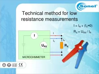
“Far” end, no plateau. V(far) V(near) Motivation • In the scenario of a beam loss there is a large charge deposition in the sensor bulk and coupling capacitors can get damaged • Punch-Through Protection (PTP) structures used at strip end to develop low impedance to the bias line and evacuate the charge But… • Measurements with a large charge injected by a laser pulse showed that the strips can still be damaged • The implant resistance effectively isolatesthe “far” end of the strip from the PTP structure leading to the large voltages
Example: HPS experience • Heavy Photon Search (HPS) is an experiment where Si sensors are intentionally put in close proximity to intense electron beam in JLab. • APV-25 as FE chips; and HPK sensors for D0 run2b: P-on-n, 10 cm long. • R(strip) ~ 1.8 MW(=> 180 kW/cm, compared to 15 kW/cm in ATLAS07). • There is a danger of beam loss with showering • the innermost strips. • => Beam test in SLAC e- beam simulating the shower. • Saw issues at higher Bias and flux. P. Hansson et al (SLAC) HPS Test Tracker • Note: The onset of problems showed up at ~ order of magnitude less flux than expected in ATLAS. But the strip resistance was 2 orders of magnitude higher! • Initially suspected damaged coupling capacitors. • Currently think FE ASICs are damaged. Miguel Ullan (CNM-Barcelona) RD50 meeting (CERN) – Nov 2013 4
Proposedsolution • To reduce the resistance of the strips on the silicon sensor. • Notpossibletoincreaseimplant doping tosignificantlylowertheresistance. Solid solubility limit of the dopant in silicon + practical technological limits (~ 1 x 1020 cm-3) • Alternative: deposition of Aluminum (Metal 1) on top of the implant: • R□(Al) ~ 0.04 W/□ 20W/cm Standard Low-R
Technology • Metal layer deposition on top of the implant (first metal)before the coupling capacitance is defined (second metal). • Double-metal processing to form the coupling capacitor • A layer of high-quality dielectric is needed between metals. • Deposited on top of the first Aluminum (not grown) • Low temperature processing needed not to degrade Al: T < 400 ºC
Technology • Initial experiments with MIM capacitors • Low temperature deposited isolation: • Plasma Enhanced CVD (PECVD): Process at 300-400 ºC • > 20 pF/cm ~ 3000 Å • 3 technological options: Silane: 3000 Å of SiH4-based silicon oxide (SiO2) deposited in 2 steps. TEOS: 3000 Å of TEOS-based oxide deposited in 2 steps (“Tetra-EtilOrto-Silicate”) Nitride: 1200+1200+1200 Å of TEOS ox. + Si3N4 + SiH4 ox. (Tri-layer) • Yield results for the largest caps (> 1 mm2): Best for nitride Less pinholes due to Tri-layer
s Bias rail p d s Poly gate Implant Design • PTP design: • Design of experiments (DOE): varying p, s d • Wafer design: • 10 ATLAS-barrel-like sensors: “LowR sensors” • 64 channels, ~2.3 mm long strips • First metal connected to the strip implant to reduce Rstrip • Each sensor with a different PTP geometry (with polysiliconbridge) • 10 extra standard sensors for reference (no metal in implant). Identical design to the LowR but without metal strip on top of the implant
Wafer 07 LowR sensors Wafer 07 Standard sensors Firstbatchgeneral tests • IV measurements, sensors were scanned from 0 to 600 V. • CV, VFD, Bias resistor (RBIAS), coupling capacitance (CCOUP), Inter-strip resistance, … • Both standard and LowR sensors show similar general characteristics. • R(implant) is reduced by ~3 orders of magnitude: 13.6 kW/cm (standard) 23 W/cm (LowR).
Bias pad0 V DC pad20 V ~ 0 V ~ 20 V PTP zone Bias pad0 V DC pad40 V Breakdown zone ~ 0 V ~ 40 V PTP zone Breakdown zone Firstbatch PTP tests • PTP tests show unexpected behavior: • Breakdown voltage independent of PTP structure geometry • at ~40 V in standard sensors and at ~20 V in LowR sensors • Oxide breakdown at a different place in the strip occurs before PTP is activated. • Thin oxides overlooked during fabrication • Only critical when PTP structures are present and tested Standard Low R
Pulse shape in #electrons Standard LowR Pulse shape • Concerns about possible pulse shape change in LowR sensors • Standard and LowR sensors are tested with the ALIBAVA System and an IR laser. • Each sensor is read by one Beetle ASIC • Pulse shape with the sensor fully depleted. The pulse shapes are identical for standard and LowR detectors with a small, negligible difference at the peak
Laser PTP: initialtests • We also evaluated dynamic response with laser tests. • The oxide issue notwithstanding, the laser tests show that the low strip resistance technology equalizes the potential along the strip, as intended. J. Wortman et al (UCSC) standard Low-R Much reduced DV along the strip for Low-R sensors Similar effect at reduced light intensity where the signals plateau in the safe range. standard Low-R
New batch • New batch being processed correcting this: • Thicker thermal oxide in the coupling capacitor area to avoid breakdown in standard sensors • Thicker and tri-layer oxide deposited between poly and metal in LowR sensors to avoid breakdown in LowR sensors • In some extra sensors, new metal mask (METAL-B) with no metal on top of bias resistor area to avoid the possibility of breakdown in that area • Some wafers will have a reduced p-stop doping to make sure we have PTP • The process is well advanced. We expect the wafers ready for middle of December
Additionalsolutions • Other methods to obtain LowR sensors being studied: • TiSi2: allows the use of high temperature steps after the oxide deposition oxide densification higher yield • Highly doped polysilicon: allows the growth of thermal oxide after it high quality oxide back to “standard” process
TitaniumSilicide (TiSi2) • TiSi2 formation technology at CNM • Goodformation of TiSi2layer • Lowsheetresistance: ~1.2 Ω/ • Densification at 900 ºC, 30 min • Selfalignedprocess • TiSi2MiM capacitors fabricated • 100 % yield up to 20 V • More tests up to 100 V • Risk of higherleakagecurrentsbecause TiSi2layer «consumes» Si. • Polysilicon-Metal capacitors to be fabricated next
Conclusions • Lowresistivitystrips (LowR) proposedtoprotectstripsensors in theevent of a beamlossmakingthe PTP more effective • FirstimplementationwithAluminumlayer in contactwiththeimplanttodrastically reduce stripresistance • LowRsensors show similar behavior as standardsensors • Initialdinamic laser tests show aneffectivereduction of theimplantvoltage • New batchbeingprocessedtoovercome a technologicalproblem in thefirstbatchthatprevents full test • New possibleimplementationsbeingtriedwithTiSi2 and polysilicon to assure a better coupling capacitor formation, and a more standard processing