Download
1 / 24
260 likes | 483 Views
Molecular Beam Epitaxy of Low Resistance Polycrystalline P-Type GaSb. Y. Dong , D. Scott, Y. Wei, A.C. Gossard and M. Rodwell. Department of Electrical and Computer Engineering, University of California, Santa Barbara.

E N D
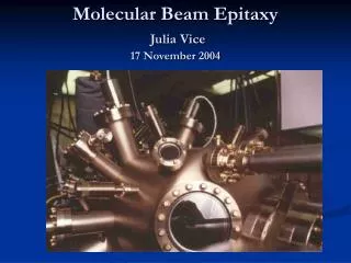
Molecular Beam Epitaxy of Low Resistance Polycrystalline P-Type GaSb Y. Dong, D. Scott, Y. Wei, A.C. Gossard and M. Rodwell. Department of Electrical and Computer Engineering, University of California, Santa Barbara yingda@ece.ucsb.edu 1-805-893-3812 15th IPRM 2003 Santa Barbara, CA
Outline • Motivations • Polycrystalline material for InP HBT’s extrinsic base • Why choose GaSb • MBE growth of Poly-GaSb • Electrical Properties of Poly-GaSb • Conclusions
InP Vs SiGe HBTs Advantages of InP HBTs over SiGe HBTs~20:1 lower base sheet resistance, ~ 5:1 higher base electron diffusivity~ 3:1 higher collector electron velocity, ~ 4:1 higher breakdown-at same ft. However, InP HBTs have not provided decisive advantages over SiGe HBTs in mixed-signal ICs.
Strong Features of Si/SiGe HBT Process • Highly scaled • Very narrow active junction areas • Very low device parasitics • High speed • Low emitter resistance using wide n+ polysilicon contact • Low base resistance using large extrinsic polysilicon contact • High-yield, planar processing • High levels of integration • LSI and VLSI capabilities
Polycrystalline Base Contact SiGe HBT process: extensive use of poly-Si for base contact • The Advantages of Polycrystalline Base Contact: • Reduce the B-C capacitance by allowing metal-to-base contact over the field oxide • Reduce the base resistance by highly doping the polycrystalline extrinsic base High Maximum Oscillation Frequency (Fmax), ECL logic speed… Low CBC, RBB Can a similar technology be developed for InP HBTs ?
N - c o l l e c t o r N - c o l l e c t o r N + s u b c o l l e c t o r N + s u b c o l l e c t o r S . I . s u b s t r a t e S . I . s u b s t r a t e Polycrystalline Base Contact in InP HBTs 2) Collector pedestal etch, isolation, SiO2 planarization 1) Epitaxial growth SiO2
Extrinsic base SiN Base Metal SiO2 Intrinsic base 4 SiO2 N- collector N- collector N + s u b c o l l e c t o r S . I . s u b s t r a t e N + s u b c o l l e c t o r S . I . s u b s t r a t e Polycrystalline Base Contact in InP HBTs 4) Deposit base metal, encapsulate with SiN, pattern base and form SiN Sidewalls 3) Base Regrowth
Emitter contact InAlAs/InGaAs emitter SiN Collector contact Base metal P++ extrinsic base N- collector SiO2 N + s u b c o l l e c t o r S . I . s u b s t r a t e Polycrystalline Base Contact in InP HBTs 5) Regrow InAlAS/InGaAs emitter
Properties of Polycrystalline Material • Small crystallites join together at grain boundaries • Inside each crystallite: single crystal • At grain boundaries: a large number of traps Fermi level pinned Polycrystalline InAs Polycrystalline GaSb
Ec Ev Ef Grain boundary Ec Ev Ef Grain boundary Material Choices for Polycrystalline Base • Polycrysalline material choices: • GaAs • Wide bandgap low hole mobility • Fermi level pinned in mid-bandgap large band-bending barrier • GaSb • Narrow bandgap high hole mobiliy • Fermi-level pinned on valence band • InSb • Narrow bandgap • low melting point (~520 οC) Can not withstand emitter regrowth Schematic diagram of suggested energy band structure near grain boundary in p-type of GaAs and GaSb
1) 3000Å SiO2 deposited on Semi-insulating GaAs by PECVD. • 2) Poly-GaSb samples were grown in a Varian Gen II system. • Sb source valved and cracked • CBr4 delivered through high vacuum leak vavle • Growth rate fixed at 0.2 μm/hr Poly-GaSb SiO2 3000Å MBE Growth of Polycrystalline GaSb GaAs
Influence of V/III Beam Flux Ratio • Hole mobility changes little with V/III ratio • Hole concentration increases with decreasing V/III ratio (Reason: Carbon must displace antimony to be effective p-type dopant)
Influence of Growth Temperature • Hole concentration changes little with growth temperature • Hole mobility decreases with growth temperature
Grain Size’s Temperature Dependence SEM pictures of poly-GaSb samples Polycrystalline GaSb Grown at 520 οC Gain size: ~350nm Polycrystalline GaSb Grown at 475 οC Grain size: ~100nm
Poly-GaSb’s Grain Size and Resistivity • Grain size increases steadily with growth temperature • Resistivity increases rapidly when grain size exceeds the film thickness
Ec Ev Ef Grain boundary Small Grain Vs. Large Grain • Small grain: • More grain boundaries for carriers to cross • Larger total boundary areas connecting crystallites • Large grain: • Fewer grain boundaries for carriers to cross • Smaller total boundary areas connecting crystallites Small band bending barrier Total connecting boundary area more important
Grain Size Vs Film Thickness When the film thickness approaches the grain size, the total connecting boundary area will be significantly reduced Rapid resistivity increase SiO2
Thickness Dependence Bulk resistivity has strong dependence on film thickness Sheet resistivity increases very fast with decreasing thickness
Comparison Between Poly-GaSb and Poly-GaAs With similar carbon doping level, grain size and film thickness, the resistivity of poly-GaSb’s resistivity is more than one order of magnitude lower than that of poly-GaAs.
Conclusions • Poly-GaSb proposed to be used as extrinsic base material for InP HBTs • Low resistance poly-GaSb films can be achieved by MBE growth using CBr4 doping • The resistivity of poly-GaSb has strong dependence on film’s thickness and grain size, particularly when the film thickness is comparable with the grain size.
Acknowledgement This work was supported by the DARPA—TFAST program