Download
1 / 20
310 likes | 522 Views
This methodology provides a platform-centric view and static architecture description aligned to the DIE Framework, reflecting as-is capability for 2004. Developed in MS Office, it serves as a foundation for the NCW project.

E N D
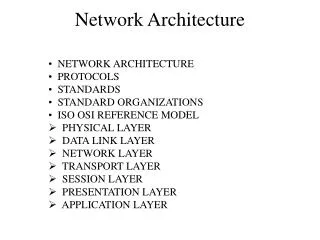
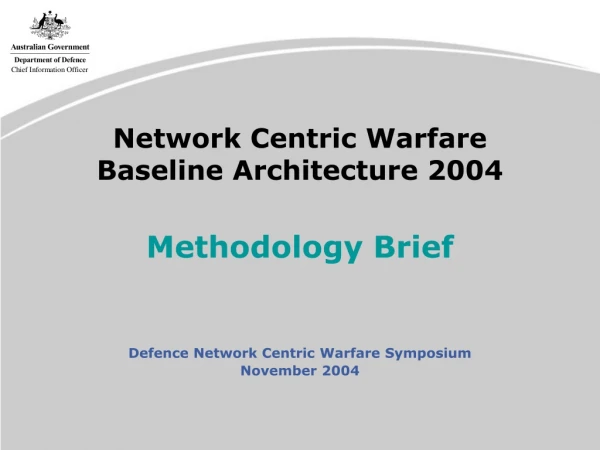
Network Centric Warfare Baseline Architecture 2004 Methodology Brief Defence Network Centric Warfare Symposium November 2004
Scope • Hybrid view modified from the USMC EF • Aligned to the DIE Framework • Draws on the NCW Roadmap • Platform-centric view • Static architecture description • Reflect as-is capability for 2004 • Based on a Regional Aggression Scenario • Developed in MS Office (Excel) • Three weeks of Development • One week of validation • Limited access to SME in timeframe
Approach • Does not follow the ‘purist’ EA development approach • Represents a hybrid view of selected DAF products • OV 1 Concept Graphic • OV2 Node Connectivity Diagram • OV3 Information Exchange Requirements (Banded) • OV4 Command Relationship Chart • OV5 Activity Description (NCW Aspirational) • SV2 Systems Communication Description • Gives the ‘customer’ what is needed for the NCW Project Office Workshops
FA C2 FP FD FG IS NMO NCW Aspirational Roles Force Generation and Sustainment Information Superiority and Support Non-Military Operations Force Application Command and Control Force Protection Force Deployment
Data User Applications Common Services User Devices Systems Hardware Networks/Datalinks Bearers DIE FrameworkDefence Information Infrastructure
Command Data Control User Applications Situational Awareness Common Services Shape User Devices Targeting SREW Systems Hardware Intelligence Networks/Datalinks Support / Quality of Life Bearers Logistics Management Information Banding Structure
NTDS BCSS PMKeyS LotusNotes ACSS eMailClient GCSS-M SOCCS JCSE MHS JCSS SOEApps SDSS JISS ROMAN User Applications Data User Applications Common Services User Devices Systems Hardware Networks/Datalinks Bearers
Common Services Intra / Inter Net SOE (Servers) Data User Applications DSN DRN Other Common Services User Devices Systems Hardware Networks/Datalinks Messaging (DISCON) Bearers Not a lot of activity identified in the 2004 architecture
User Devices Ruggedised Laptop MILSPEC Wagtail Data User Applications Phone Spitfire Common Services User Devices Raven Parakeet Systems Hardware Networks/Datalinks Fax Bearers CryptoDevice This part of the architecture needs to be validated in the workshop.
Systems Hardware / Datalinks DEFSATStation LAN Router HeloData Link Switches ARC 190 Data Parakeet DNOC ELMA HF User Applications Common Services User Devices GCSS-M KY 900 KU 838 Systems Hardware Networks/Datalinks Link 11 ARC 186 ARC 164 Bearers MHS INMARSAT ASKY-1 OTCIXS Link 4
Networks and Bearers SHF Mobilsat UHF Parakeet Data Air Band User Applications Common Services User Devices VHF Bde Tac Voice Systems Hardware Networks/Datalinks Air Band Bearers HF Ship-Shore DEFCOMSTA Fixed PSTN on NII
Vertical Layout Concept Graphic Area of Operations Operational Entity NCW Roles Information Flows User Applications Common Services User Devices Systems Hardware Bearers, Networks
Amphibious AO MOLE Fwd Mounting Base Deployed Higher HQ Task Force AUS Littoral Australian Support Area SLOC Mounting Base Horizontal Layout
Purpose • Validate the baseline for 2004 • Foundation for mapping DCP to operational domain of DII • Basis for developing a 2010 architecture • Basis for developing dynamic models in other tools
Screen Shots Example: Deployed Bde HQ Combination of Military Symbols and Icons / Clip Art
Screen Shots Example: Bde HQ to JTFHQ Cmd Link User App : JCSS Common Svc : DRN / DSN User Devices : Raven & Parakeet To HF Bearer
Screen Shots Example: FFH User Devices Systems Hardware
Screen Shots Example: Brigade All Levels Shown
Network Centric Warfare Baseline Architecture 2004 John Ramsay Director DIE Architecture Support R8-3-22, Russell Offices, Canberra, ACT Tel: +616 6265 7023 john.ramsay@defence.gov.au