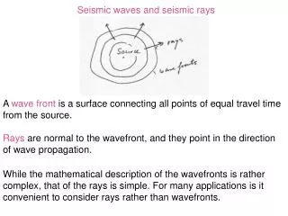
Designer Seismic VSP
390 likes | 927 Views
Designer Seismic VSP. Ernie Majer (LBNL) J. Queen ( Hi –Q Geophysics) T. Dalely (LBNL) Roy Long ( DOE) . Acknowlegements. Whiting Oil and Gas Company U.S. DOE Oil and Gas Program. Goal of Microhole Seismic Methods. Active Seismic

Designer Seismic VSP
E N D
Presentation Transcript
Designer Seismic VSP Ernie Majer (LBNL) J. Queen ( Hi –Q Geophysics) T. Dalely (LBNL) Roy Long ( DOE)
Acknowlegements • Whiting Oil and Gas Company • U.S. DOE Oil and Gas Program
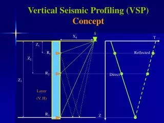
Goal of Microhole Seismic Methods • Active Seismic • Define fine scale structure and lithology controlling fluid flow and content • Fracture flow versus matrix flow • Fault locations, bedding, pinch outs, compartment size and geometry, etc. • Discriminate fluid type and content in near and long term • Oil/water/gas interface • CO2, steam, water drive efficiency, etc • Cost effective!!! • Passive Seismic • Low cost means to monitor dynamics of reservoir as fluid is produced and/or injected • Hydrofracture creation • Interaction in the long and short term of natural fractures with induced fractures • Effect and interaction of reservoir properties with changing stress • Provide validation of reservoir manipulation
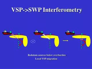
Weathered Zone Deep Targets CO2 Project Results at Teapot Dome, WY Using VSP Microhole Technology (Ref. October, 2006 Issue of SEG’s Leading Edge – “Cost-effective imaging ofCO2 injection with borehole seismic methods”: http://tle.geoscienceworld.org/ Note: Modified from Kinder Morgan CO2 LP Company
Micro-Electromechanical Systems (MEMS) Microhole Technologies for Imaging Field DeployedMEMS Geophone Array • Changes the way we explore for oil and gas • Changes the way we monitor EOR projects
Demonstrate Microhole/Downward Looking VSPLANL/LBNL Objective • Demonstrate improved highresolution active seismic(uses man-made sound source) • Demonstrate cost effectivenessof shallow, low cost, VSPinstrument boreholes for continuous monitoring withactive and passive seismic(uses naturally occurringsound source) Accomplishments • Shallow Microhole VSP “sees” up to 4 times (or more) shallow hole depth • Up to three times better resolution than VSP in conventionally drilled boreholes (much better signal to noise ratio) Benefits • Permits use of microholes for low cost, rapid VSP deployment because sensors do not need to be placed at reservoir level • High resolution seismic surveys can be faster and much cheaper with permanently installed shallow, instrument boreholes • Cost effective, permanent VSP boreholes could revolutionize complex reservoir characterization and long term EOR monitoring
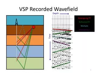
RMOTC VSP compared to Surface Seismic Approximate hole depth Shannon 1st wall creek Zero Offset Microwell VSP 6000 feet 2nd wall creek Lakota Red peak Tensleep
Whiting VSP/Monitoring • Purpose • Apply Microhole VSP to focus on areas of uncertainty • Examine litholgy and heterogenety • Valdate location of features controlling CO2 migration • Linements • Continuity of lithology • Detect changes in seismic due to CO2 ( time lapse) • Approach • Apply VSP in at least three microholes (ended up with 5) • Apply passive monitoring to determine effect of fluids on stress • Logistics • No surface lines necessary • All recording performed at VSP Well
Noise Versus Depthfor Microhole Noise Level at 500 feet Depth Is 60 dB Less Than Surface Noise
Wickett Field CO2 Start-Up Area (Phase 1), Section 19 of GWO Lease
CO2 Sequestration Project Inject CO2 along 2 lines Drive Oil to wells between lines Monitor CO2 injection with Time Lapse Microhole 3D seismic survey
Geophone Installation Completed Microwell
Acquisition DesignReflection Point Density(assumes uniform velocity)
Acquisition DesignReflection Points(assumes uniform velocity)
August 2007 Vibroseis Source 10 – 100 Hz 5 sweeps 2 ms sample rate 231 Shot Points 5 Wells 1,155 VSP's ~275,000 traces Two Surveys after CO 2 Injection was Started - Summary • February 2007 • Vibroseis Source • 10 – 100 Hz • 5 sweeps • 2 ms sample rate • 165 Shot Points • 5 Wells • 825 VSP's • ~200,000 traces
Frequency Content FFT Results for 5 Depths Between 313' & 380' SP 710 to MW_04
2-D Processing Line 7 Shot Points 701 – 713 Wells 1 and 4 Line 5 Shot Points 501 – 535 Wells 3, 4, 5, &6
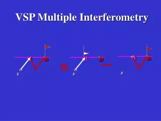
Processing for Time Lapse Reflection Amplitude Change • Apply static shifts from explosive shot monitor. Edit noisy traces, sort by depth, etc. • Use F-K filters to remove downgoing and enhance upgoing energy. • Obtain reflection section for pre and post data • For time-lapse change: normalize reflection amplitude using a shallower reflector above the Frio. • Calculate change in reflection amplitude
Line 7 Time Lapse Analysis Approach: • Compare Old and New VSP Migrations • Pick Horizon at ~ -570' on Both Data Sets • Bright event above reservoir interval • Flatten Both Data Sets to Common Depth • Normalize Old Amplitudes • Calculate RMS amp. for picked event on both data sets • Multiply entire Old data set by ratio of RMSnew/RMSold for picked event • Difference the Old and New Data
Data After Flattening to Common Depth Flattened Depth Yates Tops from Well GWO-156 OLD NEW
Difference Plot of Old – New After Flatten and Normalize Yates Tops from Well GWO-156 Largest Differences Show Up Here
Line 5 Time Lapse Analysis Approach: • Compare Old and New VSP Migrations • Pick Horizon at ~ -410' on Both Data Sets • Bright event above reservoir interval • Flatten Both Data Sets to Common Depth • Normalize Old Amplitudes • Calculate RMS amp. for picked event on both data sets • Multiply entire Old data set by ratio of RMSnew/RMSold for picked event • Difference the Old and New Data
Comparison of Old and New Line 5 VSP Depth Migration Results Reservoir Interval OLD NEW
Data After Normalizing Old Amplitudes Flattened Horizon Yates Tops from Well GWO-156 OLD Flattened Horizon Yates Tops from Well GWO-156 NEW
Difference Plot of Old – New After Flatten and Normalize Yates Tops from Well GWO-156
Future Work • Develop Microhole drilling technology • Refine and develop processing technology (time lapse acquisition) • Improve sensors and acquisition capability
Next Generation Sensors Wide Bband Width: DC – Kilohertz High Sensitivity: 10X Current 2008 Technology Low Cost