Download
1 / 9
100 likes | 143 Views
This report presents methods and parameters for interpreting Flat Dilatometer Test (DMT) data to characterize ground properties accurately. It includes details on inserting the blade, interpreted parameters such as friction angle and undrained shear strength, and recommendations for settlement prediction and compaction control. The text also covers comparisons with field vane and cone wedge distortions in clay, detection of slip surfaces in slopes, and the significance of constrained modulus data.

E N D
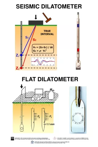
SEISMIC DILATOMETER FLAT DILATOMETER TC16 (1997). “The DMT in soil Investigations”, a report by the ISSMGE Technical Committee tc16 ON Ground Property, Characterization from in-situ testing, 41 pp. EUROCODE 7 (1997). Standard Test Method, European Committee for Standardization Part 3: Design Assisted by Field Testing, Section 9: FLAT DILATOMETER TEST (DMT), 9 pp. ASTM (2002). Standard Test Method D6635-01, American Society for Testing and Materials The standard test method for performing the Flat Dilatometer Test (DMT), 14 pp.
Torpedo L 3 m WAYS OF INSERTING THE BLADE Pushed by truck Pushed by a drill rig Driven by a drill rig Driven or pushed by a static/dynamic penetrometer Pushed from a fixed platform Driven by SPT Tripod “TORPEDO” INSERTION METHOD
LEGEND Z = Depth Below Ground Level Po,P1,P2 = Corrected A,B,C readings Id = Material Index Ed = Dilatometer modulus Ud = Pore Press. Index Gamma = Bulk unit weight Sigma' = Effective overb. Stress Uo = Pore pressure INTERPRETED PARAMETERS Phi = Safe floor value Friction Angle Ko = In situ earth press. coeff. M = Constrained modulus (at Sigma') Cu = Undrained shear strength Ocr = Overconsolidation ratio SHEAR WAVE VELOCITY Z A B C Po P1 P2 Gamma Sigma' Uo Id Kd Ed Ud Ko Ocr Phi M Cu D1 (m) (kPa) (kPa) (kPa) (kPa) (kPa) (kPa) (kN/m^3) (kPa) (kPa) (MPa) (Deg) (MPa) (kPa) DESCRIPTION 0.6 105 330 121 320 15.7 10 0 1.66 11.8 6.9 41 18.4 SANDY SILT 0.8 73 255 91 245 15.7 13 0 1.70 6.8 5.4 39 11.4 SANDY SILT 1.0 81 350 94 340 16.7 16 0 2.61 5.7 8.5 38 17.1 SILTY SAND 1.2 76 267 93 257 15.7 18 2 1.80 5.1 5.7 37 10.6 SANDY SILT 1.8 33 135 55 125 15.7 21 8 1.50 2.2 2.4 2.5 SANDY SILT 2.0 119 225 140 215 15.7 23 10 0.57 5.8 2.6 1.3 5.3 5.0 19 SILTY CLAY 2.2 117 201 140 191 15.7 24 12 0.40 5.4 1.8 1.2 4.7 3.3 18 SILTY CLAY 2.4 106 173 129 163 14.7 25 14 0.29 4.6 1.2 1.1 3.7 2.0 16 MUD 2.6 115 185 138 175 15.7 26 16 0.30 4.7 1.3 1.1 3.8 2.2 17 CLAY 2.8 112 178 135 168 14.7 27 18 0.28 4.4 1.1 1.0 3.4 1.9 16 MUD 3.0 111 177 134 167 14.7 28 20 0.28 4.1 1.1 1.0 3.1 1.8 15 MUD ………………………………….. 28.0 785 955 803 945 17.7 186 265 0.26 2.9 4.9 0.76 1.8 6.1 65 CLAY 28.2 795 915 816 905 16.7 187 267 0.16 2.9 3.1 0.77 1.8 3.8 66 CLAY 28.4 805 995 822 985 17.7 189 269 0.29 2.9 5.6 0.77 1.8 7.0 67 CLAY 28.6 800 985 817 975 17.7 190 271 0.29 2.9 5.5 0.76 1.8 6.7 66 CLAY 28.8 790 945 809 935 17.7 192 273 0.23 2.8 4.4 0.74 1.7 5.2 64 CLAY 29.0 790 955 808 945 17.7 193 275 0.26 2.8 4.7 0.73 1.7 5.6 64 CLAY 29.2 755 1070 766 1060 17.7 195 277 0.60 2.5 10.2 0.67 1.4 11.1 57 CLAYEY SILT 29.4 795 950 814 940 17.7 196 279 0.24 2.7 4.4 0.72 1.6 5.1 64 CLAY 29.6 850 1070 866 1060 17.7 198 281 0.33 3.0 6.7 0.77 1.8 8.4 71 SILTY CLAY 29.8 845 1015 863 1005 17.7 200 283 0.24 2.9 4.9 0.76 1.8 6.1 70 CLAY 30.0 890 1050 909 1040 17.7 201 284 0.21 3.1 4.6 0.81 2.0 5.9 77 CLAY Vs (m/s) SDMT TEST RESULTS DMT TABULAR OUTPUT
SETTLEMENT PREDICTION Bullock & Failmezger (Porto 2004) CONE WEDGE DISTORTIONS IN CLAY
Landslide in Milazzzo, Sicily SLIDING 1 RECONSOLIDATION 3 DETECTING SLIP SURFACES IN A SLOPE (NC STATE) REMOULDING 2 INSPECT KD 4 PROFILE COMPACTION CONTROL MDMT (kPa) DMT reflects more sensitively compaction benefits and modulus increase Depth Z(m) LIQUEFACTION RECOMMENDATIONS Kd limits for safety vs liquefaction For magnitude = 7.5 earthquake HRELAXATION BEHIND A LANDSLIDE ’Horizontal Stress kPa Absolute Elevations (m) 1 1 2 3 2 3
Cu comparisons Field Vane at Skeena Ontario Canada National Site BOTHKENNAR UK National Site FUCINO ITALY kPa kPa 0 5 Z (m) 10 Z (m) 15 20 A.G.I., 10th ECSMFE Firenze 1991 Vol. 1, p. 37 Nash et al., Géotechnique, June 1995, p. 173 Mekechuk 1983 Cu in Recife Clay – BrazilUniv. of Pernambuco Research Site 1 Malaysian Clays Wong, J.T.F. & Dobie, M.J.D. 1990 Coutinho et al., Atlanta ISC 1999 M comparisons M in Tokyo Bay Clay SITES IN VIRGINIA, U.S.A. ONSOY Clay (NORWAY) CONSTRAINED MODULUS M (MPa) CONSTRAINED MODULUS M (MPa) Z (m) Geotechnical Research Center Kiso-Jiban Consultants Co., Tokyo Norwegian Geotechnical Institute (1986)."In Situ Site Investigation Techniques and interpretation for offshore practice" Report 40019-28 by S. Lacasse, Fig. 16a, 8 Sept 86 FAILMEZGER, 1999
SDMT SISMOGRAMS Z(m) AS RECORDED RE-PHASED 9.0 9.5 10.0 10.5 11.0 11.5 12.0 12.5 13.0
SDMT REPEATABILITY Each Vs corresponds to a single blow of the hammer Differences of Vs: 1 m/s VALIDATION SDMT at FUCINO Research Site June 2004