Download
1 / 17
170 likes | 314 Views
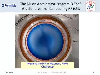
201 MHz NC RF Cavity R&D for Muon Cooling Channels. Derun Li Center for Beam Physics International Neutrino Factory Workshop WG-3, Frascati, Italy June 21-26, 2005. Outline. Introduction Ionization cooling Requirements of RF cavities for muon cooling RF cavity R&D activities

E N D
201 MHz NC RF Cavity R&D for Muon Cooling Channels Derun Li Center for Beam Physics International Neutrino Factory Workshop WG-3, Frascati, Italy June 21-26, 2005
Outline • Introduction • Ionization cooling • Requirements of RF cavities for muon cooling • RF cavity R&D activities • 805 MHz cavity • 201 MHz cavity • Status of the prototype cavity • Be window R&D • RF Couplers • Summary
Introduction Ionization cooling principle LH Absorbers RF Cavities • Strong magnetic field to confine muon beams • Lose energy in LH absorbers • High gradient RF cavities to compensate for lost longitudinal energy
RF Cavity for Muon Cooling Requirements: • Intense muon beams • Have short lifetime and large phase space • Interact weakly with matter • Confined in focusing channels • High gradients • 17 MV/m at 201 MHz and 34 MV/m at 805 MHz • Normal conducting Rounded closed “pillbox” cavity Large and thinBe foils (low-Z) to terminate RF fields • High cavity shunt impedance • Low peak surface field • High accelerating efficiency with independent phase control • Less RF power
Lab G Magnet (MTA) 805 MHz cavity inside NCRF Cavity R&D Activities Experimental studies using an 805 MHz pillbox cavity with demountable windows at MTA (Lab G), FNAL • Achievable accelerating gradient is a function of external B • Be windows withstand high field without surface damage • How to interpolate the results to 201 MHz cavities? • Does this apply to 201 MHz cavities?
201 MHz Prototype Cavity Goal: Design, build a 201-MHz cavity with large Be windows, and condition and operate it at 16+ MV/m in a few Tesla magnetic field Cavity and its sub-components • Cavity body + water cooling lines • Four ports and flanges • RF loop couplers • Cavity support structure • Cavity tuners • Ceramic RF windows (~ 4”) • Curved Be windows • Possible LN temperature operation Cavity design concept Layout of water cooling lines on cavity
The 201 MHz Cavity Parameters The cavity design parameters • Frequency: 201.25 MHz • β = 0.87 • Shunt impedance (VT2/P): ~ 22 MΩ/m • Quality factor (Q0): ~ 53,000 • Curved Be window with radius and thickness: 21-cm and 0.38-mm Nominal parameters for cooling channels in a neutrino factory • For up to ~16 MV/m peak accelerating gradient • Peak input RF power ~ 4.6 MW per cavity (assuming 85% of Q0 and 3 times filling time) • Average power dissipation per cavity ~ 8.4 kW • Average power dissipation per Be window ~ 100 watts
We have successfully developed extruding technique for port pulling over e-beam joints The Cavity Fabrication Finished equator welding E-Beam Welding of Stiffener Ring at J-Lab
The Cavity + Sub-components Loop coupler Finished cavity port Ceramic RF window
EP at J-Lab After 1st EP run last week (June 2005) U-Shape Electrode
Current Status & Near Term Plans • Continue EP at J-Lab • High pressure water rinsing • Vacuum Assembly and base pressure measurement • Packing and Shipping • Couplers, RF probes, gauges and vacuum pump assembly at the MTA, FNAL • Baking at the MTA, FNAL • RF conditioning (Ti-N coated copper windows to start with) without magnetic field
Curved Be Windows for 201 MHz Cavity • Succeeded in two curved Be windows for the 805-MHz cavity • Placed purchase order of three Be windows for 201-MHz cavity: • 0.38 mm thick, 420 mm diameter • at Brush-Wellman (~100 watts per window with ∆T~ 55 degrees at nominal Study-II parameters) • Window is formed by applying a die at elevated temperature • Copper frame is brazed to Be window • Be windows will be Ti-N coated • Present a perfect conducting BC for RF. • Min. scattering and mechanically strong 420 mm 420 mm diameter curved Be window for the 201 MHz cavity formed at Brush-Wellman. The formed Be foil is sandwiched (brazed) in two annular Cu frames • The curved Be window status: • warping (1st one) • cracking (2nd) on edge, but usable • Two good windows already • To be Ti-N coated
RF Coupler Design and Status • Loop couplers at critical coupling • Prototype coupling loop design uses standard off-the-shelf copper co-axial components • Coupling loop has integrated cooling lines • Two SNS style RF windows mfg. by Toshiba received (no cost to us !) • Two couplers with RF windows are complete • High power tested up to 600 kW in TW mode and 2.4 MW (peak) in SW mode • Ready to ship to MTA, FNAL • Bellows connection required on MICE cooling channel (Study-II) for thermal and dimensional reasons Ceramic RF window Loop coupler
Load RF Power Two couplers Coupler Conditioning The two Couplers • Conditioning started in the week of May 16, 2005 at SNS • Good vacuum ~ low 10-8 T • Achieved 600 kW in TW mode (matched load) • Achieved 10 kW average power (~ 9 kW average for nominal NF parameters) • Achieved 2.4 MW peak power in SW mode (at variable short positions) • Ceramic windows work fine in nearly two weeks of the RF conditioning
Mucool Test Area (MTA) 805-MHz 201-MHz Facility to test all components of cooling channel, not ionization cooling • At high beam power • Designed to accommodate full Linac Beam • 1.6 X 10¹³p/pulse @15 Hz • 2.4 X 10¹⁴ p/s • RF power from Linac: 201 and 805 MHz test stands • Waveguides pipe power to MTA • Clean room ordered • On site assembly of windows • Currently plan to operate either RF or LH2/H2 tests, but not both simultaneously. • 805 MHz experimental study • will resume soon • 201 MHz cavity expect to • arrive next month
Eight 201 MHz Cavities for MICE Two SC coupling Coils Power couplers Eight 201 MHz cavities The 201 MHz prototype cavity is the baseline design for MICE
Summary • MTA is ready to accept high power RF test programs • 805 MHz experimental programs will resume soon at MTA, FNAL • 201 MHz prototype cavity progress well and expect to be shipped to MTA, FNAL for high power tests next month (July 2005) • Significant progress on fabrication of curved Be windows • RF couplers have been high power tested and ready for assembly at the MTA, FNAL • MUCOOL 201 MHz cavity is the baseline design for MICE