Download
1 / 13
140 likes | 545 Views
325 MHz RF Cave and SC Spoke Cavity Tests. Robyn Madrak – Accelerator Physics Center (APC) for the HINS/Project X Group. Single Spoke Resonator (SSR) Cavities. SSR1: 325 MHz, b = 0.22 superconducting cavities Init design for the proton driver/HINS pulsed linac (3ms, 1% DF), 4K

E N D
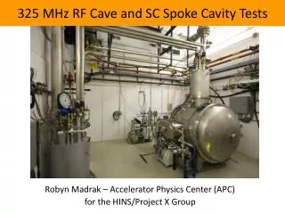
325 MHz RF Cave and SC Spoke Cavity Tests Robyn Madrak – Accelerator Physics Center (APC) for the HINS/Project X Group
Single Spoke Resonator (SSR) Cavities • SSR1: 325 MHz, b = 0.22 superconducting cavities • Init design for the proton driver/HINS pulsed linac (3ms, 1% DF), 4K • Now being incorporated into design for the Project X CW linac, 2K • Two SSR1 cavities have been fully fabricated (1 – Zanon, 2 – Roark) Robyn Madrak - APC
Dressed SSR1 Cutaway of cavity, He vessel Robyn Madrak - APC
Cryostat in SCTF Test Cave • Cryostat has B field shield • X-ray detectors • Diodes inside of cryostat • FOXES and Chipmunks outside 80 K shield Coils for B field test Nitrogen line Coupler port vacuum line He line 1.44 m OD Robyn Madrak - APC
SSR1-01 Test History • Tested first in VTS at 4K and 2K, bare, CW. • Tested CW at SCTF, dressed (these results) • Measured cavity Q0 vs. E, max Eacc, Xray activity vs E • Q disease test (dependence of Q on cooldown time) • Cavity df/dP (frequency sensitivity to pressure fluctuations) • Lorentz Force detuning coefficient • Sensitivity to external magnetic fields (Q degradation) • Fast Tuner tests (microphonics compensation, etc.) • Tested Pulsed • Test of cavity along with design coupler • Max Eacc • Tuner compensation for LFD during pulse • Future upgrade planned: 2K operation Robyn Madrak - APC
SCTF, Q0vs E, CW tests, high Qext Measured by chipmunks, outside of cryostat, ~1m from cavity Quench limited, ~ 27 MV/m T = 4.7 K Design: Q0 at 10 MV/m = 5e8 Robyn Madrak - APC
Tuner Tests/Pressure Sensitivity • Measured df/dP = -145 ± 15 Hz/torr (sim predicted 210 Hz/torr) • Lorentz force detuning coefficient : 1.5 ± 0.5 Hz/(MV/m)2 (sim predicted 3.8 Hz/(MV/m)2) • ProjX Cavity BW 20-200 Hz ; HINS initially ~400 Hz; here ~2Hz Fast Tuner Pressure Compensation • Good results with fast tuners for pressure fluct. compensation: 8 Hz variation w/lock compared to 300 Hz w/o lock ~ 300 Hz variation w/o lock ~ 8 Hz variation w/ lock YuriyPischalnikov, Warren Schappert
Q Disease • Is a drop in Q due to the formation of hydrides during cooldown • Effects can be minimized by a fast cooldown • ‘Sensitive’ temperature region is 150 – 70 K • Typically does not appear during the ‘first’ cooldown after chemical processing • Can possibly be ‘cured’ (or minimized) by hydrogen degassing (baking at 600C) followed by flash BCP • Was observed on SSR1-01 in the VTS: saw x 8 drop in Q at 4.4 K with 7 hour hold at 100 K Robyn Madrak - APC
Q Disease in the VTS VTS ~ factor of 8 drop in Q after 7 hour hold @100 K From Ristoriet. al , ‘Development of 325 MHz Single Spoke Resonators for HINS at Fermilab: Recent Results PAC ‘09
Q Disease at SCTF • After VTS, SSR1-01 Hydrogen degassed (600 C bake) at Jlab • Q drops but drop is small (~20% drop) minimal Q disease; baking was a success • Will be more sensitive at 2K – awaiting upgrade to test this Note: Q in second cooldown same as in 1stcooldown 3 hours in sensitive region 11 hours in sensitive region Robyn Madrak - APC
Magnetic Field Sensitivity Tests • Project X – will likely have solenoids for beam focusing near the cavities test sensitivity of cavities to B field (look for Q drop) • Installed two coils on each end of the cavity • Quench cavity 5000X in 8-10 G Bfield • Measured Q at high and low field – no degradation I I
High Power Pulsed Tests w/Design Coupler • 1st pulsed test, 1st test with power coupler: QL ~1e6 • Reached 36.5 MV/m with ~2ms flattop • ~40 MV/m quench limit for short pulse • Fast tuner tests - piezos: (Pischalnikov, Schappert) • Lorentz Force detuning ~3kHz peak to peak w/no compensation • Piezo compensation reduces f drift to ~50 Hz during pulse f drift during pulse f (Hz)
Summary • 1st CW – dressed tests were a success for the facility and for SSR1 • Cavity Q vs E and max Eaccexceed design requirements • 600 deg C bake (thanks to Jlab) good results at 4K, need studies at 2K • Fast tuners compensate well for microphonics , LFD • Magnetic field sensitivity results are encouraging. No effect due to quenching with field >50X expected fringe field • Pulsed tests of coupler/cavity satisfactory, high max Eacc during pulsed testing • 2 K tests in the not-so-distant future Robyn Madrak - APC