Download
1 / 16
160 likes | 340 Views
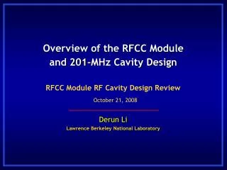
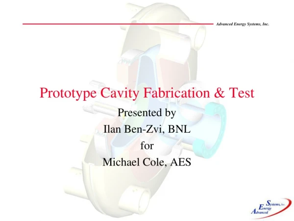
201 MHz Cavity Fabrication Update. Derun Li Lawrence Berkeley National Lab. MICE CM24 at RAL, UK June 1, 2009. SC coupling Coil. Curved Be window. Cavity Couplers. Vacuum Pump. 201-MHz cavity. Four RF Cavities in each RFCC Module. RFCC PDR and FDR completed during CM21 and CM22

E N D
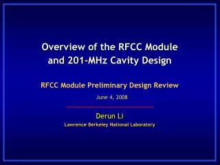
201 MHz Cavity Fabrication Update Derun Li Lawrence Berkeley National Lab MICE CM24 at RAL, UK June 1, 2009
SC coupling Coil Curved Be window Cavity Couplers Vacuum Pump 201-MHz cavity Four RF Cavities in each RFCC Module Derun Li - Lawrence Berkeley National Lab – June 1, 2009
RFCC PDR and FDR completed during CM21 and CM22 201 MHz cavity detailed design and analysis were complete at CM23 Qualification of three cavity fab vendors completed late last year RFP for cavity fabrication released by LBNL in January 2009 Copper cavity material arrived at LBNL in January 2009 Cavity fabrication has been awarded to Applied Fusion in Feb. 2009 Cavity body fabrication started in April 2009 A slight reduction in cavity diameter to raise the frequency has been specified and analyzed Visited ACME Spinning re-spun two spare half shells to the new cavity profile and measured frequency shifts Developed cavity body fabrication procedures (based on lessons learned from the MuCool prototype) The first 5 cavities to be delivered by end of CY2009 with option to purchase 5 additional cavities Progress Summary (1/2) Derun Li - Lawrence Berkeley National Lab – June 1, 2009
Other components: Cavity tuner RF & structural analyses and CAD model are in progress Structural analyses of cavity suspension system is complete RF coupler based on design previously developed for MuCool cavity Ceramic RF windows (SNS window, off-shelf component) Cavity cooling water feed-through concept has been developed Beryllium windows Purchase order placed with Brush Wellman Company Cavity and vacuum vessel interface with CC In progress Progress Summary (2/2) Derun Li - Lawrence Berkeley National Lab – June 1, 2009
Update on MICE RF Cavity Design • 3-Dimensional RF cavity parameterized model to study frequency shifts from RF ports and curved Be windows and Epeak • Frequencies variation between cavities should be within 100 kHz • Fabrication • Modification of the mold for prototype cavity • Reduction in diameter to raise the MICE cavity frequency • Tune cavities close to design frequency by deformation of cavity body (if needed) • Fine tuners operate in the push-and-pull mode 230 kHz Derun Li - Lawrence Berkeley National Lab – June 1, 2009
Cavity Design Parameters • The cavity design parameters • Frequency: 201.25 MHz • β = 0.87 • Shunt impedance (VT2/P): ~ 22 MΩ/m • Quality factor (Q0): ~ 53,500 • Be window diameter and thickness: 42-cm and 0.38-mm • Nominal parameters forMICEand cooling channels in a neutrino factory • 8 MV/m(~16 MV/m)peak accelerating field • Peak input RF power:1 MW(~4.6 MW)per cavity • Average power dissipation per cavity:1 kW(~8.4 kW) • Average power dissipation per Be window:12 w(~100 w) Derun Li - Lawrence Berkeley National Lab – June 1, 2009
201 MHz Cavity Concept Spinning of half shells using thin copper sheets and e-beam welding to join the shells; extruding of four ports; each cavity has two pre-curved beryllium windows, but also accommodates different windows Derun Li - Lawrence Berkeley National Lab – June 1, 2009
Visit to ACME Spinning in April 2009 (1/3) • Machined the MuCool mold to the new profile • Re-spun the two half spare shells to new profile • Measured frequency shifts before and after spinning Expected frequency shift ~ 1 MHz Measurements: Shell #1: 197.275 MHz (before) 198.180 MHz (after) Derun Li - Lawrence Berkeley National Lab – June 1, 2009
Visit to ACME Spinning in April 2009 (2/3) • Spun and measured a new half shell (frequency: 198.415 MHz) • Developed a fabrication procedure • Pre-polishing copper sheets • Inspecting the surface • Polishing visible scratches locally if necessary (before and after) • Handling and shipping Polished surface Local polishing to remove deeper scratches Surface inspection during the spinning Derun Li - Lawrence Berkeley National Lab – June 1, 2009
Visit to ACME Spinning in April 2009 (3/3) • Spinning of MICE cavity (April 22, 2009): Derun Li - Lawrence Berkeley National Lab – June 1, 2009
Cavity Inspection at LBNL (1/2) • 12 spun half shells arrived LBNL in May 2009 • CMM scans to pair best matches of two half shells in diameters, 8 of them have been measured so far Center hole for handling & spinning Polished cavity surface Labeling each shell Derun Li - Lawrence Berkeley National Lab – June 1, 2009
Cavity Inspection at LBNL (2/2) • CMM scans to pair best matches of two half shells (diameters) • Over 1,500 points along the cavity perimeter • Find the best match of average radii, radius deviations and the location of the deviation angles • Examples of two shells Radius deviations are magnified by a factor of 55 here Shell 4B (blue) and 6B (yellow) Derun Li - Lawrence Berkeley National Lab – June 1, 2009
Fabrication Status at Applied Fusion (1/2) • Fixtures used for the MuCool prototype shipped to Applied Fusion • Two re-spun half shells arrived Applied Fusion in early May for fabrication test/practice • E-beam welding tests • Stiffener rings • Equator • Port extruding • Water cooling pipes E-beam welding of the stiffener ring Derun Li - Lawrence Berkeley National Lab – June 1, 2009
Fabrication Status at Applied Fusion (2/2) Port extruding and flange welding testing E-beam strength testing Derun Li - Lawrence Berkeley National Lab – June 1, 2009
Current Plan at Applied Fusion • June – September 2009: • Machine the shells and prep for EB • EBW stiffener rings • Equator welding • Port extruding (4 in each cavity) • Machine and weld port flanges • Machine-finish and EBW of the nose rings • Machine-finish and EBW of the nose rings • Tig-weld water cooling pipes • Vacuum check of the cavity and water cooling pipes Integration of cavities, coupling coils and other module components will take place at LBNL Derun Li - Lawrence Berkeley National Lab – June 1, 2009
Schedule Summary (Presented at CM23) Derun Li - Lawrence Berkeley National Lab – June 1, 2009