RF Power R&D
RF Power R&D. David Wildman May10 , 2005. Slides “borrowed” from: G. W. Foster, A. Moretti, D. Sun, I. Terechkine, D.Wildman,& D. Wolff. Outline. System Overview 325 MHz Klystron Modulator for Klystron I/Q Modulators Phase Shifters (3 Types) Conclusions. 325 MHz RF System.

RF Power R&D
E N D
Presentation Transcript
RF Power R&D David Wildman May10 , 2005 Slides “borrowed” from: G. W. Foster, A. Moretti, D. Sun, I. Terechkine, D.Wildman,& D. Wolff
Outline • System Overview • 325 MHz Klystron • Modulator for Klystron • I/Q Modulators • Phase Shifters (3 Types) • Conclusions wildman - AAC Meeting
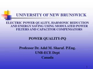
Toshiba E374A High Power Amplifier Klystron Tube is designed for particle Accelerators. Tube tunable to 325 MHz: Tube is in production for J-Parc; 17 tubes have recently been delivered to J-Parc. Power Output = 3.0 MW Gain = 50 dB Efficiency = 55 % Duty Factor = 2.6% Toshiba factory test at 1.5 ms 4.5 ms test done at Fermilab wildman - AAC Meeting
Klystron Status • Negotiations are in the final stages for the purchase of one 325 MHz klystron from Toshiba. • Toshiba is quoting a delivery date of March 2006. wildman - AAC Meeting
Proton Driver Modulator Requirements • Purpose: Provide the pulsed power needed for Klystron operation • Specifications • Pulse width: 4.5 ms • Pulse Voltage: 120 kV • Pulse Current: 140 amps • Repetition rate: 2.5 Hz • Average Power 225 kW • Support operation for both MBK and TOSHIBA 325 MHz klystrons • Allow cost effective redeployment to 1.5ms operation wildman - AAC Meeting
Fermi-built TESLA Modulator • 3 Modulators built in 1990s • Specifications (PD) • Pulse width: 1.7 ms (4.5) • Pulse Voltage: 120 kV • Pulse Current: 130 amps (140) • Repetition rate: 10 Hz (2.5) • Average Power 300 kW (225) • First modulator has run for 25,000 hours (since 1993) • Second and third modulators have run for 18,000 hours each (since 1996) wildman - AAC Meeting
Modifications to Fermi Modulator for PD • Changes needed to meet spec • 3x larger cap bank • 3x larger “Bouncer” Circuit • 3x larger pulse transformer • Changes to reduce cost • Traction type capacitors Used extensively in Europe and SNS modulators • 1.6kV IGBTs replace with 3.3kV units (SLAC collaboration) • Back-up switch plus fast crowbar replaced with redundant, fail-safe switch. • Updated controls wildman - AAC Meeting
4.5 ms Modulator Simplified Diagram wildman - AAC Meeting
Modulator Construction Schedule • EE Support is in the process of building 2 modulators for SMTF. • Requisitions for capacitors and pulse transformers have been awarded. • The first unit should be finished by the end of this year. wildman - AAC Meeting
CAUTION We are now going from one type of modulator to another! wildman - AAC Meeting
I/Q modulator box (stripline structure) Box size: 24” x 20” wildman - AAC Meeting
325 MHz I/Q Modulator Specifications • Power (peak/average, duty factor 1.5%) • 40 kW/ 600 W • 150-200 kW/ 2.25-3 kW • 650 kW/9.75 kW (1 feed option for RFQ) • Tuning Range • Phase: +/- 45 degree • Amplitude: +/- 1.5 dB • Phase Tuner Slew Rate • 1 degree/1sec wildman - AAC Meeting
325 MHz I/Q Modulator R&D Program • Determine what type of rf structure (stripline, coaxial or waveguide) should be used for each power level. • Demonstrate fast tuning capability. • Solve potential technical issues: rf breakdown, cooling, and ferrite stability. • Simplify assembly and cost reduction. • Goal: to be ready when klystron arrives. wildman - AAC Meeting
325 MHz I/Q Modulator • The Plan • Low power level (40 kW) • Use stripline structure to build a joined hybrid and circulator into one box with 4 coaxial ports. • Power test this device with coaxial phase shifter at Argonne. • Medium power (150 kW) • Power test a coaxial structure • High power level (650 kW) • This is a special case. • First evaluate the number of rf feeds for RFQ to determine the power level • Then choose structure: either waveguide (magic tee) or coax wildman - AAC Meeting
325 MHz I/Q Modulator • Status • Low power level (40 kW) • Preliminary design of circulator and hybrid (circuit simulation and 3D E-M simulation) is done. • A prototype circulator using available ferrite disks is built and measured: achieved low insertion loss (-0.06 dB) and high isolation (-27 dB) • Received new ferrite disks to adjust the frequency of the circulator. wildman - AAC Meeting
Prototype Circulator wildman - AAC Meeting
Approaching the Phase Shifter Problem • Develop and test waveguide-based phase shifter; • Test the coaxial phase shifter available at FNAL • Work with a vendor to build an I/Q modulator wildman - AAC Meeting
Amplitude and Phase (IQ) Modulator Yttrium Iron Garnet • Ferrite Shifters can be built based on: • Coaxial line, • Strip-line, • Waveguide 1 2 • = (1+2)/2 = (2-1)/2 wildman - AAC Meeting
Performance Requirements Frequency: 1300 MHz ± 1 MHz Phase Change: ± 45° RF Power Ratings: 550 kW Peak, 1.5 ms, 10 Hz 550 kW Peak, 4.5 ms, 3.3 Hz Insertion Loss: less than 0.2 dB Response time: time constant ~ 30 s Flange: WR-650 wildman - AAC Meeting
Waveguide Phase Shifter Coil Core • Main design issues: • High power operation • Heat management • Tuning range • Response time wildman - AAC Meeting
Phase Shifter Mockup Low Level RF Measurements Results of the low level RF measurements are in a good agreement with modeling (HFSS) wildman - AAC Meeting
High Power Test A0 1300 MHz Klystron T = 250 µsec F = 5 Hz Existing A0 interface was used for testing wildman - AAC Meeting
High Power Test at 1300 MHz • Two methods of phase measurements: • Oscilloscope measurements • Using available IQ modulator Available phase zone is limited by sparking that develops near the resonance frequencies SF6 added Max Power - 2000 kW (req. 600 kW) Phase shift - ~ 80° (req. 90° ) wildman - AAC Meeting
Why Choose a Coaxial Design? • Usable over a wide frequency range • Unlike waveguide has no cutoff frequency • Same shifter could be used at both 325 MHz and1300 MHz • Easy to understand- TEM modes • Compact : smaller size is generally good but leads to higher fields • Modified 3 1/8” coax line, fully filled with aluminum doped yttrium-iron garnet wildman - AAC Meeting
Phase Shift & Transmission Phase Shift @ 325 MHz Transmission @ 325 MHz • S11 measurement of 10 TCI cores wildman - AAC Meeting
Fast Response of Shifter @325 MHz - 5 cores Bias Current 100A/Div Phase Shift ~15 Deg/Div wildman - AAC Meeting
High Power Test @ 1300 MHz wildman - AAC Meeting
Phase Shift During 352MHz, 100kW Pulse Phase Shift from mixer Forward Power wildman - AAC Meeting
Coaxial Phase Shifter • Coax design is preferred • at 325MHz • In-house design tested to 660kW at 1300 MHz • Tested at 300 kW at Argonne with APS 352MHz Klystron • Fast coil and flux return should respond in ~50us wildman - AAC Meeting
Advanced Ferrite Technology GmbH (AFT) Products: High Power CirculatorsFast Ferrite TunerFast High Power Phase ShifterHybrid Tuner SystemsFerrite MaterialElectrical Power Suppliesfor high power inductive loads The IQ modulator from AFT is expected in May: 1 Magic Tee; 1 straight waveguide section; 2 waveguide - coax transition; 2 FFT´s directly connecting to the transition; 1 control unit for setting phase and amplitude and feedback loop; 1 dual directional coupler for amplitude control; 1 arc detection system. Power supply will be provided by FNAL wildman - AAC Meeting
Phase Shifter Conclusions • The prototype of a waveguide-based, 1.3 GHz phase shifter shows excellent maximal power and acceptable phase shift performance. • Coaxial phase shifter meets peak power and phase shift requirements both at 1300 MHz and 325 MHz. • Commercial prototype of an I/Q modulator due this month. • Average power testing, reaction time testing, and IQ modulator modeling should be the next steps of the R&D wildman - AAC Meeting
General Conclusions • We’ve made a good start on our R&D program • We still have a lot of work to do before the Toshiba klystron arrives next March. wildman - AAC Meeting