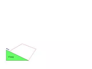
Efficient Vacuum Clamp Assembly for Secure PCB Machining and Debris Management
The vacuum clamp assembly is designed to create negative pressure for securely holding work pieces during machining processes. This system allows for user-friendly setup and effectively holds work pieces post-cutting while collecting debris. It provides solutions for board warpage issues. Compared to a shop vac, the quieter vacuum pump has a low flow rate, eliminating leaks and debris interference, though it is costly. In contrast, the shop vac is affordable, has a high flow rate, and doubles as a debris management system, though it is noisy. Our prototype analysis shows significant clamping force for precise PCB handling.


Efficient Vacuum Clamp Assembly for Secure PCB Machining and Debris Management
E N D
Presentation Transcript
Vacuum Clamp Assembly • A system that creates negative pressure to hold down work pieces during machining • Will allow for easy set up by user • Work pieces will be held down after being cut • Collect debris being cut from board • Corrects for board warpage
Vacuum Clamp- Shopvac vs Pump Vacuum Pump + Quieter than shopvac - Can be expensive - Very low flow rate(~10 cfm) - Could not have any leaks in system - Could not allow debris to reach vacuum pump Shopvac + More affordable + Very high flow rate(150+ cfm) + Could share vacuum with debris management system. + Allows for leaks in system + Also acts as a debris management system - High noise level
Vacuum clamp calculations About 2.5 lbf is supplied from each hole. In a feasibility test, our prototype had 16 holes. A total of 40 lbf was applied to the PCB.
Registration System on Vacuum Clamp Assembly • Particularly important for zeroing a double sided PCB board • Ability to hold the board more securely and flip the board halfway through • Pins help restrict translational degrees of freedom and z-axis rotation and allow for realignment when flipping the board over • Pin holes can be incorporated into the PCB design • At least 2 pins needed, possibly up to 4 Process 1.PCB is secured to vacuum table 2.A number 57 bit (42 mil) is inserted into the mill and can drill holes the size of a push pin 3.Drill alignment holes for reference pins 4.Stop the mill and insert pins through holes into sacrificial layer 5.Mill one side, flip the board over, and re-pin