Download
1 / 33
340 likes | 583 Views
Development of a Closed Loop Control System for Two Dimensional Vibration Assisted Machining. by Heisum Ewad Advanced Manufacturing Technology Research Laboratory, GERI, Liverpool John Moores University E-mail: h.ewad@2011.ljmu.ac.uk. Outlines. Introduction Literature review

E N D
Development of a Closed LoopControl System for Two Dimensional Vibration Assisted Machining by Heisum Ewad Advanced Manufacturing Technology Research Laboratory, GERI, Liverpool John Moores University E-mail: h.ewad@2011.ljmu.ac.uk
Outlines • Introduction • Literature review • Project Aims &Objectives • Control System • Preliminary Results • Experimental Setup • System calibration • Conclusion • Plan for Further work
Introduction to Grinding Types of grinding Grinding is an operation in which material is removed from the workpiece by a powered wheel. An abrasive material rubs against the metal part and removes tiny pieces of material. In manufacturing high precision parts with tight tolerances are obtained by grinding. Internal grinding Centerless grinding Cylindrical grinding Surface grinding Grinding wheel is composed of an abrasive grits clustered together with special bound. Types of Abrasives: Natural: Emery, Corundum, Diamonds Synthetic: (SiC)Silicon carbide, Aluminium Oxide (Al2O3), Cubic Boron Nitride (CBN)
Introduction to Grinding Grinding is a popular method of material removal Construction Aviation & Automotive Optical lenses Giant telescope mirrors
Introduction to Grinding Wide range of wheels Size and shape depends on the purposes.
Grinding Forces In precision grinding operations, the magnitude of cutting forces is important since it affects the workpiece quality. The magnitude of cutting forces can be affected by different factors such as the material properties, the tool geometry, the table speed, depth of cut and grinding fluids. The grinding force (F) is made of the tangential and the normal components. • Normal Force (Fn) Has an influence on the surface deformation. • Tangential Force (Ft) Affects the power consumption and service life of the wheel. The ratio Ft / Fn determine the interfacial friction VS Fn F Vw: Workpiece Velocity Vs: Wheel Velocity Vw Ft Workpiece
Project Aim & Objectives Design, model, build and control a two dimensional piezo actuator for the grinding/machining operation. Objectives Aims Initial Development of a controller for one axis Implement control strategy within Matlab & Labview Design two dimensional controller for two axis in Matlab Design a Phase shifter to achieve oriented elliptical oscillation Implement control strategy within Matlab & Labview to control the jigs Experimental work
Industry Requirement Manufacturing makes ever-increasing demands for higher machining speeds. Vibration is used in various technological processes to improve the performance of the machines by exploiting intelligently the synergy of the oscillations.
Why Vibration In Grinding? • Reduction of cutting forces. • Better coolant delivery over the entire contact zone. • Better heat removal from the grinding zone. • Oscillation allows the grains to cut with more than one edge. • Oscillation reduces the load per grain therefore, reduces the wheel wear. • Better surface finish due to lapping / polishing effect Shelf-SharpeningProcess of the Wheel
Limited material is available on vibration assisted grinding. The reason being that vibration is thought to be harmful to grinding process. Indeed uncontrolled vibration creates chatter and lead to surface deterioration. Zhong et al (2004), showed the usefulness of vibration assisted grinding. Below is his complex design used to generate micro-vibration in surface grinding of silicon wafer. -initial results showed improved surface and reduced normal force. Literature Zhong et al (2004)
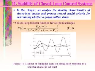
In Grinding silicon Zhang used: Wheel speed: 33 m/s Workspeed: 16 mm/s Depth of cut: 5, 10, 30 μm Vibration frequency 200 Hz Amplitude : 10 μm Literature • Results showed: • Reduction in normal force • Improve surface roughness • Low surface temperature • Little reduction in tangential force Cutting Force in VA grinding Surface roughness in VA grinding (Zhang et al 2006)
Literature Vibrations Devices Materials: • Piezo-ceramic (Lead zirconate titanate) • Terfenol-d (alloy of Terbium, Dysprosium, and Iron) Devices: • Electro-dynamic Shakers • Piezoelectric Actuators • Ultrasonic Vibration Devices Produces very high magnetostriction. Very High Force and Displacement.
Literature Electrodynamic shakers have a permanent magnet and create vibration by moving a coil when alternating electric power is applied. Shakers are used in diverse activities such as product evaluation, stress screening, squeak-and-rattle testing and modal analysis. Three Functional Limits: • Displacement • Acceleration • Velocity
Literature Piezoelectric actuators are devices that produce oscillations by the expansion and contraction of piezo elements depending on the applied voltage. They are driven by the output voltage of a power amplifier that amplifies a small sinusoidal input signal from a function generator. Advantages Features • They perform sub-nanometer moves at high frequencies. • No rotating or sliding parts to cause friction. • They can move high loads up to several tons. • Do not require maintenance because of no-moving parts. Principle of Piezo-actuator
Control System: Theory • The goal of controller is to make the system performs in a pre-defined and desired manner. • Control systems are basically classified as: • open Loop and Closed Loop • Open-loop control system
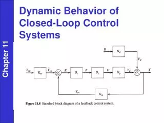
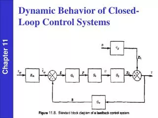
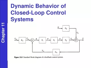
Control System : Theory • Closed-loop control system
Control System : Theory PID PID stands for Proportional, Integral and Derivative. Controllers are designed to eliminate the need for continuous operation attention. • P Proportional band =100/gain • I Integral = 1/reset (units of time) • D Derivative = rate =pre-act (units of time) • KP to decrease the peak time. • KD to reduce the overshoot and settling time. • KI to eliminate the steady-state error.
Preliminary Results System motion A mathematical was derived from the actual oscillating jig designed for the preliminary investigation. The equations of motion of the system are as follows:
Preliminary Results Control System- Flow Chart
Preliminary Results Control System: Open-Loop The system was developed using SIMULINK toolbox in MATLAB
Preliminary Results Control System: Closed-Loop Controller Response
Experimental Setup System Set up in open Loop Control • No feedback • No measurement for the actual output • Does not respond to load variation • Does not respond to disturbances
Experimental Setup System Set up in Closed Loop Control
Data Logging In Labview Front panel of data Acquisition In Labview
Equipments – Abwood 5025 machine Machine Specification
Calibration Result • Dynamometer: Measuring Range: 10 kN
Stiffness Test of the Spindle Unit The dynamic stiffness is important in machine tool design. It can improve the quality of the work-piece Stiffness K = 16.67 N/μm Compliance C = 1/k = 1/16.67 = 0.059 μm/N Vaios, 2010
Experimental Configuration Grinding wheel Workpiece Accelerometer for closed loop control Self-contained oscillating jig 3-Axis Kistler dynamometer type 9257A
Experimental Configuration Oscilloscope Power Amplifier Data Acquisition system (Labview) Grinding machine Self-contained oscillating jig Power Supply DAQ Assistant
Equipments – Vibro-HEDG machine Machine Specification Further experimental work will be carried out on the new Vibro-HEDG machine.
Conclusions • Literature review has been carried out but still on-going • A mathematical model of the system motion was derived • An initial closed loop control for one axis was developed in Matlab/simulink and required fine tuning in actual grinding • The 3axis kistler dynamometer has been calibrated for force measurement • An initial grinding experimental was planned but postponed due to problems with machine tool main power supply. This will resume when the machine tools are powered.
Work Plan for 6 months • Grinding tests with single axis oscillation in axial direction of the wheel. • Fine tuning of the model based on experimental results in grinding • Development of control system for the 2nd axis in the tangential direction. • Grinding tests with two independently oscillating axes. • Data collection from experimental work for full development of directional controlled oscillation.