Download
1 / 27
280 likes | 777 Views
Using FLUENT in Design & Optimization. Devendra Ghate, Amitay Isaacs, K Sudhakar, A G Marathe, P M Mujumdar. Centre for Aerospace Systems Design and Engineering Department of Aerospace Engineering, IIT Bombay http://www.casde.iitb.ac.in/. Outline. CFD in design Problem statement

E N D
Using FLUENT in Design & Optimization Devendra Ghate, Amitay Isaacs, K Sudhakar, A G Marathe, P M Mujumdar Centre for Aerospace Systems Design and Engineering Department of Aerospace Engineering, IIT Bombay http://www.casde.iitb.ac.in/
Outline • CFD in design • Problem statement • Duct parametrization • Flow solution • Results • Conclusion FLUENT CFD Conference 2003
Using CFD in Design • Simulation Time • CFD is takes huge amounts of time for real life problems • Design requires repetitive runs of disciplinary analyses • Integration • With optimizer • With other disciplinary analyses (e.g. grid generator) • Automation • No user interaction should be required for simulation • Gradient Information • No commercial CFD solvers provide gradient information • Computationally expensive and problematic ( ) to get gradient information for CFD solvers (finite difference, automatic differentiation) FLUENT CFD Conference 2003
Problem Specification New parameters Parametrization Geometry Generation Grid Generation CFD problem setup Flow Solution Methodology Optimization using Surrogate Models (RSM, DACE) FLUENT CFD Conference 2003
Problem Specification Parametrization CFD problem setup Flow Solution Methodology New parameters Geometry Generation Optimization using Surrogate Models (RSM, DACE) Grid Generation FLUENT FLUENT CFD Conference 2003
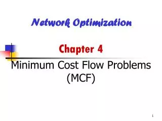
Geometry of duct from Entry to Exit ? 3-D Duct Design Problem Entry Exit Location and shape known • Pressure Recovery • Distortion • Swirl FLUENT CFD Conference 2003
Y Z X X Duct Centerline • Control / Design Variables • Ym, Zm • AL/3, A2L/3 A X Cross Sectional Area Parametrization FLUENT CFD Conference 2003
Y Z X X Duct Centerline • Control / Design Variables • Ym, Zm • AL/3, A2L/3 A X Cross Sectional Area Parametrization(contd.) FLUENT CFD Conference 2003
Typical 3D-Ducts FLUENT CFD Conference 2003
Grid Generation Clustering Parameters • Complete grid generation process is automated and does not require human intervention • Complete control over • Distance of the first cell from the wall • Clustering • Number of grid points Generation of entry and exit sections using GAMBIT Mesh file Conversion of file format to CGNS using FLUENT Entry & Exit sections Generation of structured volume grid using parametrization Grid parameters Conversion of structured grid to unstructured format FLUENT CFD Conference 2003
Turbulence Modeling • Relevance: Time per Solution • Following aspects of the flow were of interest: • Boundary layer development • Flow Separation (if any) • Turbulence Development • Literature Survey • Doyle Knight, Smith, Harloff, Loeffer • Circular cross-section • S-shaped duct • Baldwin-Lomax model (Algebraic model) • Computationally inexpensive than more sophisticated models • Known to give non-accurate results for boundary layer separation etc. • k- realizable turbulence model • Two equation model • Study by Devaki Ravi Kumar & Sujata Bandyopadhyay (FLUENT Inc.) FLUENT CFD Conference 2003
Turbulence Modeling (contd.) • Standard k- model • Turbulence Viscosity Ratio exceeding 1,00,000 in 2/3 cells • Realizable k- model • Shih et. al. (1994) • Cμ is not assumed to be constant • A formulation suggested for calculating values of C1 & Cμ • Computationally little more expensive than the standard k- model Total Pressure profile at the exit section (Standard k- model) FLUENT CFD Conference 2003
Distortion Analysis • DC60 = (PA0 – P60min) /q where, PA0 - average total pressure at the section, P60min - minimum total pressure in a 600 sector, q - dynamic pressure at the cross section. • User Defined Functions (UDF) and scheme files were used to generate this information from the FLUENT case and data file. • Iterations may be stopped when the distortion values stabilize at the exit section with reasonable convergence levels. FLUENT CFD Conference 2003
Parallel Execution • Parallel mode of operation in FLUENT • 16-noded Linux cluster • Portable Batch Systems for scheduling • Batch mode operation of FLUENT (-g) • Scale up depends on grid size FLUENT CFD Conference 2003
Results: Total Pressure Profile FLUENT CFD Conference 2003
Results (contd.) • Mass imbalance: 0.17% • Energy imbalance: 0.06% • Total pressure drop: 1.42% • Various turbulence related quantities of interest at entry and exit sections: y+ at the cell center of the cells adjacent to boundary throughout the domain is around 18. FLUENT CFD Conference 2003
Slapping • Methodology • Store the solution in case & data files • Open the new case (new grid) with the old data file • Setup the problem • Solution of (0.61 0.31 1 1) duct slapped on (0.1 0.31 0.1 0.1) These are huge benefits as compared to the efforts involved. FLUENT CFD Conference 2003
Conclusion Time for simulation has been reduced to around 20% using parallel computation and slapping. • Process of geometry & grid generation has been automated requiring no interactive user input • FLUENT has been customized for easy integration into an optimization cycle • CFD analysis module ready for inclusion in optimization for a real life problem FLUENT CFD Conference 2003
Future Work • Further exploration and improvement of slapping methodology • Identification and assessment of optimum optimization algorithm FLUENT CFD Conference 2003
Thank You http://www.casde.iitb.ac.in/mdo/3d-duct/
Problem Statement • A diffusing S-shaped duct • Ambient conditions: 11Km altitude • Inlet Boundary Conditions • Total Pressure: 34500 Pa • Total Temperature: 261.4o K • Hydraulic Diameter: 0.394m • Turbulence Intensity: 5% • Outlet Boundary Conditions • Static Pressure: 31051 Pa (Calculated for the desired mass flow rate) • Hydraulic Diameter: 0.4702m • Turbulence Intensity: 5% FLUENT CFD Conference 2003
Duct Parameterization • Geometry of the duct is derived from the Mean Flow Line (MFL) • MFL is the line joining centroids of cross-sections along the duct • Any cross-section along length of the duct is normal to MFL • Cross-section area is varied parametrically • Cross-section shape in merging area is same as the exit section FLUENT CFD Conference 2003
y(Lm/2), z(Lm/2) specified Cmerger y2, z2 y(x), z(x) y1, z1 Centry x 0 Lm/2 Lm MFL Design Variables - 1 • Mean flow line (MFL) is considered as a piecewise cubic curve along the length of the duct between the entry section and merging section Lm : x-distance between the entry and merger section y1, y2, z1, z2 : cubic polynomials for y(x) and z(x) FLUENT CFD Conference 2003
MFL Design Variables - 2 • y1(x) = A0 + A1x + A2x2 + A3x3, y2(x) = B0 + B1x + B2x2 + B3x3 • z1(x) = C0 + C1x + C2x2 + C3x3, z2(x) = D0 + D1x + D2x2 + D3x3 • y1(Lm)= y2 (Lm), y1’(Lm)= y2’(Lm), y1”(Lm)= y2”(Lm) • z1(Lm)= z2 (Lm), z1’(Lm)= z2’(Lm), z1”(Lm)= z2”(Lm) • y1’(Centry) = y2’(Cmerger) = z1’ (Centry) = z2’(Cmerger) = 0 • The shape of the MFL is controlled by 2 parameters which control the y and z coordinate of centroid at Lm/2 • y(Lm/2) = y(0) + (y(L) – y(0)) αy 0 < αy < 1 • z(Lm/2) = z(0) + (z(L) – z(0)) αz 0 < αz < 1 FLUENT CFD Conference 2003
Area Design Variables – 1 • Cross-section area at any station is interpolated from the entry and exit cross-sections • A(x) = A(0) + (A(Lm)–A(0)) * β(x) • corresponding points on entry and exit sections are linearly interpolated to obtain the shape of the intermediate sections and scaled appropriately • Psection = Pentry +(Pexit - Pentry) * β FLUENT CFD Conference 2003
β(Lm/3) and β(2Lm/3) is specified β(x) β2 1 β1 0 x Lm/3 2Lm/3 Lm 0 Area Design Variables - 2 β variation is given by piecewise cubic curve as function of x A0 + A1x + A2x2 + A3x3 0 β < β1 B0 + B1x + B2x2 + B3x3 β1 β β2 C0 + C1x + C2x2 + C3x3 β2< β 1 β = FLUENT CFD Conference 2003