Download

1 / 16
160 likes | 354 Views
VLSI Testing. Binocular Bilateral Controller: A Hardware Fault Tolerant Implementation. Marylène Audet March 2001. Agenda. Goals The Binocular Controller Fault-Tolerant Designs Conclusion. Goals. Implement a binocular controller using eye movements model Design a fault-tolerant system

E N D
VLSI Testing Binocular Bilateral Controller: A Hardware Fault Tolerant Implementation Marylène Audet March 2001
Agenda • Goals • The Binocular Controller • Fault-Tolerant Designs • Conclusion
Goals • Implement a binocular controller using eye movements model • Design a fault-tolerant system • Simulate and test the controller
Conjugate Component (EC) : average direction in which eyes are pointed Vergence Component (EV) : angle subtended by two lines of sight EC = 1/2 (ER - EL) EV = (ER +EL) The Binocular Controller
The Binocular Controller (5) • Digital Implementation requires delay insertion • Slow Clock (order of KHz) • 12-bit digitized Inputs • All parameters shall be programmable via a CPU or switches • Target technology is FPGA (Xilinx) • Ref: “Binocular Coordination Providing Stable Tracking and Rapid Reorientation Using A Bilateral Controller Inspired By Nature”, Ross Wagner,PHD Thesis, McGill University, 1997 FOR MORE INFO...
Fault-Tolerant Designs • Introduction • MTBF • Triple Modular Redundancy • Self Purging Techniques • Sift-Out Modular Redundancy • Rollback Implementation or Time Redundancy • Berger and Weight-Based Codes
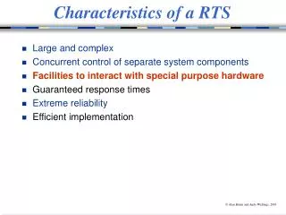
Fault-Tolerant Designs (2) • Fault-tolerant Design are used in the Military and Aerospace, Medical, Banking, etc. industries • Deep-submicron technology: compensates low yields. • Goal: Very High Reliability measured using MTBF evaluations. • Uses Concurrent Built-In Self-Test and Redundancy Techniques.
MTBF • MTBF: Mean-Time Between Failures • For example: • Processor of 100 Million Instruction Per Seconds (100 MIPS) • Reliabiltiy Factor R(t) = (0.9)12 -> 1 Failure/1012 Events • MTBF = (1012) * (10-8) = 10 000 Seconds ~ 2.7 Hours
As good as its Voter Voter must be Totally Self-Checking Redundancy cannot be tested off line -> must have a way of disabling the redundant circuit High Area Cost Module Partitioning Triple Modular Redundancy
Self-Purging: Remove Faulty Path by Comparing Problem: may require an exterrnal arbiter if there is a tie Requires feedback from Voter Sift-Out: all decision done by controller but Voter is free from controller. Self-Purging and Sift-Out
Basics: Checkpoints exists to fall-back Must have a state diagram detecting permanent faults Checker can be any encoder Rollback Implementation
Concurrent Checking / on-line. Checker detects 1->0 and 0-> 1 Transitions Errors. Checkbits can be positional (Hamming) / non-positional (Berger) within the output vector Can assign a “weight” to each output. Error Coding Techniques
Conclusion • Design Partitioning for Modular Redundancy: Adders and Multipliers • Checking Algorithm for Sift-Out Implementation • Verify against analog counterpart.