REPRESENTING GEOMETRIC CONSTRUCTIONS AS PROGRAMS
REPRESENTING GEOMETRIC CONSTRUCTIONS AS PROGRAMS. Presented by: Mohammad Shabbir Hasan shabbir5@vt.edu. Author: Bruce Sherin School of Education and Social Policy, Northwestern University. About Me. Name: Mohammad Shabbir Hasan Ph.D. Student in the CS department.

REPRESENTING GEOMETRIC CONSTRUCTIONS AS PROGRAMS
E N D
Presentation Transcript
REPRESENTING GEOMETRIC CONSTRUCTIONS AS PROGRAMS Presented by: Mohammad Shabbir Hasan shabbir5@vt.edu Author: Bruce Sherin School of Education and Social Policy, Northwestern University
About Me • Name: Mohammad Shabbir Hasan • Ph.D. Student in the CS department. • Working with Dr. Liqing Zhang in the Computational Biology and Bioinformatics Lab. • Working on predicting Insertions and Deletions (InDel) in Next Generation Sequencing data (main concentration is on Human Genome). • Obtained Masters in CS from the University of Akron, Ohio on Summer 2013. • From Bangladesh.
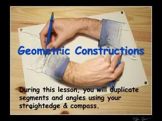
Overview • Illustrating the ways in which computer environments have transformed to the practice of mathematics or mathematics pedagogy. • Aseries of geometric constructions made in a Boxer programming environment reflecting on the resultant blended turtle geometricand dynamic geometryenvironment. • Discusses the role and potential of programmable applications and programming representation of geometric concepts and other sub-domains of mathematics.
Instructing Geometry • Two strands: • Turtle Geometry • Dynamic Geometry • In principle, they are related but in practice, they have remained relatively separate worlds.
Turtle Geometry • Had its earliest and most familiar incarnations in the Logo programming language. • Continues to live on in Logo and its descendants. • In turtle geometry activity, students write their own programs, and the constructions they create are often comparatively simple.
Dynamic Geometry • Somewhat recent than Turtle Geometry. • Students create and interact with constructions primarily though a point-and-click interface. • These environments are specifically created for geometry. • So they are extremely powerful within this domain • Allows students to make complex constructions with relative ease.
Objective of this research work • To explore briefly the merging of these two strands. • To look at how, by merging programming and dynamic geometry, “new ways of representing” familiar mathematics can be created. • To illustrate how, through the merging of dynamic geometry and turtle geometry, we may be able to create constructions that would be difficult to construct while working solely with one of the component approaches.
Tools • Programming Environment: Boxer a direct descendent of “Logo”. • It is possible in Boxer to write turtle geometry procedures using Logo’s familiar turtle graphics commands. • It also includes some modern amenities: a programming interface that is hierarchically structured as boxes within boxes (hence the name).
Example 1 • Draws a point. • Then tells the turtle to turn right 45. and go forward 50 steps • Makes a second point.
Example 2 • First draws two circles, one centered on point a and through point b, and the other centered on b and through a. • Then, in the third line of the program, the ccintcommand is used to find the intersection of the two circles. • Finally, the last line of the procedure draws a line that connects these two intersection points.
Example 3 (added some Interactivity) • Made two specific additions that are relevant here. • First, we created a command called ask-for-point. When this command is executed, the user is prompted to click somewhere in the graphics display, and a new point is then created at the indicated location. • When this program runs, the user is prompted to select locations for the two initial points. The program then joins these two points, and then constructs the bisector, just as in previous versions of bisect-ab.
Example 3 (contd.) • Second, we also added the capability for some true dynamic interaction with the graphical display. When this feature is turned on, the user can drag point a or b in our above constructions. • The figure above shows a sequence where point b has been dragged down and to the right.
Example 4 (introducing variables) • This new procedure takes two inputs, • named p1 and p2, as specified at the top of the procedure. • The procedure begins by drawing the two circles, as before. • Then it finds the intersections of these two circles and stores them in the local variable named ‘int’. • Finally, intis passed as an argument to join, and the bisector segment is drawn.
Example 5 (A compact one) • In this procedure, each of the calls to circle produce outputs that serve as the inputs to ccint. • The output of ccint(the intersection points) then, in turn, serves as the input to join.
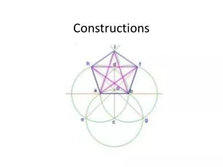
Example 6 (A more complex one) • This figure shows an example in which the compact-bisect program has been used for the construction of the centroid of a triangle. • This program constructs bisectors of two sides of the triangle. The resulting segments are then passed as inputs to the llintcommand, which finds the intersection of two given lines. • In this Figure, I have suppressed the circles in the construction for clarity.
Final Example (With turtle geometryprocedure) This procedure draws a regular polygon given two inputs, the number of sides (number-sides) and the length of a side (slength).
Final Example (with dynamic geometry sub-environment) • The revised procedure, which is shown in this Figure , takes the number of sides as one of its inputs, but the other two inputs are points that will be the endpoints of one side of the polygon. • Using these three inputs, the procedure can construct a regular polygon in which all of the vertices are labeled points. • It uses the gotoand aimtocommands to position and orient the turtle so that it is prepared to draw the remainder of the polygon, and the ml command outputs the length of the given line segment.
Conclusion • Here the author tried to establish that programming representations can be employed for geometric constructions. • Through the merging of the two approaches, some of the benefits of both turtle geometry and dynamic geometry can be achieved. Some of what is hard in dynamic geometry environments is comparatively straightforward in turtle geometry. Conversely, much of what is hard in turtle geometry is relatively easy with dynamic geometry-like tools. • If it is possible to get significant functionality by enriching programming environments, it may be possible to apply a dynamic geometry-like approach to more sub-domains within mathematics. Such environments might allow teachers and students to harness the power of computation across the range of mathematical sub-disciplines.