Geometric Constructions and Multiview Drawings
120 likes | 404 Views
Geometric Constructions and Multiview Drawings. Professor: Dr. Miguel Alonso Jr. Outline. Drawing Parallel Lines and Curves Drawing Points Dividing an Object Marking an Object at Specified Distances Orthographic Multiview Drawings Drawing Auxilary Views Construction Lines and Rays.

Geometric Constructions and Multiview Drawings
E N D
Presentation Transcript
Geometric Constructions and Multiview Drawings Professor: Dr. Miguel Alonso Jr.
Outline • Drawing Parallel Lines and Curves • Drawing Points • Dividing an Object • Marking an Object at Specified Distances • Orthographic Multiview Drawings • Drawing Auxilary Views • Construction Lines and Rays
Parallel Lines and Curves • OFFSET command • Modify->Offset, Offset button, type O • Options: Through, Erase, Layer, Multiple • POINT command • Draw->Point, Point button, type PO • Point Style: Format >Point Style
Dividing an Object • DIVIDE command • Draw>Point>Divide, type DIVIDE • Does not break an object into multiple parts • Places points where the breaks would occur • Block option, will be discussed later • MEASURE command • Draw>Point>Measure, type MEASURE • Divides the object according to a measurement at specific distances
Orthographic Multiview Drawings • Each field of drafting has its own method to present views of a product • Architecture • Plan views, exterior views, sections • Electronics • symbols • Civil • Contour lines • Mechanical • Multiview
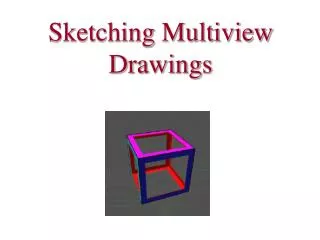
Focus on multiview • Based on the ASME Y14.3M, multiview and sectional view drawings • Orthographic Projections • Project object features onto an imaginary projection plane • Projection plane is placed parallel to the object and perpendicular to the line of sight • See fig 7-9
Six two dimensional views show all sides of an object, fig 7-10 • Imagine a cube enclosing the object, each view is made as if you were looking through each side of the cube • Front view is primary and placed in the center • Other views are placed surrounding the center view • Use only enough views to completely describe the object
Select the front view • Show hidden features, fig 7-12 • One view drawings • Showing symmetry and circle centers
Auxiliary Views and UCS • Auxiliary view is needed when a surface on the object is at an angle to the line of sight • Slanted surface is forshortened, fig 7-15 and 7-16 • UCS-user coordinate system • UCS toolbar, create new and save
Construction Lines and Rays • XLINE and RAY • XLINE extends in both directions, RAY extends in one directions • XLINE • HOR, VER, ANG, BISECT, OFFSET • RAY
Drawing problems • 2 • 4 • 10 • 13