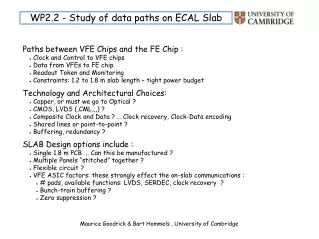
ECAL SLAB Interconnect
ECAL SLAB Interconnect. A Summary of Investigations at Cambridge. Making the interconnections between the Slab component PCBs (“ASUs”) is difficult. We have been looking at ways to do it, and testing out our ideas. The general interconnect problem

ECAL SLAB Interconnect
E N D
Presentation Transcript
ECAL SLAB Interconnect A Summary of Investigations at Cambridge • Making the interconnections between the Slab component PCBs (“ASUs”) is difficult. • We have been looking at ways to do it, and testing out our ideas. • The general interconnect problem • The way in which “Bridge” pieces could be used • The initial design work • Bits we have in hand • Investigations and first results Maurice Goodrick & Bart Hommels , University of Cambridge
DIF DIF DIF DIF DIF DIF SLAB SLAB SLAB SLAB SLAB SLAB ECAL SLAB Interconnect DAQ Architecture - Overall view ~150 VFE ASICs on each side of SLAB LDA ODR LDA LDA LDA Maurice Goodrick & Bart Hommels , University of Cambridge
ECAL SLAB Interconnect – Why Multi-Rows? How to read them out – single path or in 4 rows? ASU(n) ASU(n+1) ASU(n) Single path 4 rows Per ASU: L ~ 720mm, C ~ 72pF Per ASU: L ~ 180mm, C ~ 18pF Per Slab of 9 ASUs: L ~ 6.5m, C ~ 650pF Per Slab of 9 ASUs: L ~ 1.6m, C ~ 160pF Do these look BIG ?? Maurice Goodrick & Bart Hommels , University of Cambridge
ECAL SLAB Interconnect – Why Multi-Rows? Multi Row is aesthetically much more pleasing - but what material advantages does it offer? • Clock and Control Lines: LVDS, controlled impedance • length of each C&C trace reduced below 1/NROWS: • less signal degradation • far cleaner routing – no need for stubs • Read-Out Lines: low voltage swing CMOS • data load is shared between the rows, so lower rate needed • length (and hence capacitance) of each readout trace reduced below 1/NROWS • power for R/O reduced in same ratio The power savings not large compared to Slab power budget But achieving data rates of several Mbits/sec over complex traces of several metres length will be difficult or impossible But Multi-Rows means lots of connections - is this possible? or Maurice Goodrick & Bart Hommels , University of Cambridge
ECAL SLAB Interconnect We have been looking at using “Bridges” to jumper multiple connections between adjacent ASUs The Bridge would be soldered onto pads on the ASU (or DIF) PCB Each Bridge would provide 30-40 connections Up to 4 Bridges fit in the width of an ASU … 1 per path would be an ideal solution Maurice Goodrick & Bart Hommels , University of Cambridge
ECAL SLAB Interconnect Short FFC (Flat,Flexible-Cable) Bridges make connections on a 1mm pitch – OK for at least 120 connections Solder FFC-Bridge Track 800um ASU ASU Alternatively the Bridges can be thin PCBs, also with 1mm pitch connections. This gives a mechanical as well as electrical joint PCB-Bridge Solder Track 800um ASU ASU Maurice Goodrick & Bart Hommels , University of Cambridge
ECAL SLAB Interconnect – Bridge advantages • Provides copious connections (4 x 35 across ASU) • plenty for Power Planes • would allow 4 or more rows of connections • Solder joints well proven electrically • Signal transmission likely to be less compromised • Rework possible • Using an FFC-Bridge would make the mechanical joint independent: this might appeal to the mechanical designers • Using a PCB-Bridge combines mechanical and electrical joint Maurice Goodrick & Bart Hommels , University of Cambridge
ECAL SLAB Interconnect – Where we are The following slides give a glimpse of what we have … and some results Maurice Goodrick & Bart Hommels , University of Cambridge
ECAL SLAB Interconnect – Where we are Top View Thin traces on Kapton backing Under View FFC-Bridges: we have 250 cut, 250 on roll Maurice Goodrick & Bart Hommels , University of Cambridge
ECAL SLAB Interconnect – Where we are Top View Variant A Variant B Variant C Variant D Variant E Variant F Variant A Variant B Variant C Variant D Variant E Variant F Under View PCB-Bridges: have 15 Panels of 8 lots of 6 variants Maurice Goodrick & Bart Hommels , University of Cambridge
ECAL SLAB Interconnect – Where we are Top View Interconnect region 400um 4 identical rows of differential tracks connecting 36 way interconnect pads on left and right 180 x 180mm – as current ASU size Central region thickened to 800um Can be sliced into 4 sections, so provides for many trials Differential tracks have a range of spacings & other charcteristics to test signal propagation and cross-talk ASU-Test PCB: we have 15 Maurice Goodrick & Bart Hommels , University of Cambridge
ECAL SLAB Interconnect – Where we are PCB-Bridges: solder pasting Maurice Goodrick & Bart Hommels , University of Cambridge
ECAL SLAB Interconnect – Where we are 3 bits of ASU-Test being joined: reflow of 2nd and 3rd Using the IR Re-work station Maurice Goodrick & Bart Hommels , University of Cambridge
ECAL SLAB Interconnect – Where we are 4 Section ASU-Test Assembly FFC-Bridge joints LVDS Drive Circuit PCB-Bridge joint View of FFC-Bridge joint ASU-Test: 4 Section Assembly Maurice Goodrick & Bart Hommels , University of Cambridge
ECAL SLAB Interconnect – Where we are Re-flowing a PCB-Bridge Linear Halogen Lamp Elliptical Reflector Imaging Halogen IR Source: first test Maurice Goodrick & Bart Hommels , University of Cambridge
ECAL SLAB Interconnect: Conclusions • There are major advantages in using Bridges: • Removes major bottleneck in number of connections • Promises greater reliability • Rework likely to be easier • There’s a lot to be done: • We are trying out many things • LAL Mechanical Prototype will also test PCB-Bridge mechanics • We are finding answers: • 1mm pitch connections with continuity and no shorts • IR re-flow looking very good: • ERSA Re-work station OK • Home-brew Imaging IR source may fit well into large-scale assembly procedures: full width re-flow, multiple heads,… Maurice Goodrick & Bart Hommels , University of Cambridge
ECAL SLAB Interconnect – Where we are PCB-Bridges: half-via variant Maurice Goodrick & Bart Hommels , University of Cambridge