Download
1 / 33
330 likes | 514 Views
SLHC, ATLAS considerations. D.Lissauer, N.Hessey, M.Nessi. General. We understood from all interactions we had over the last 12 months that for a effective 25 ns solution (or even 50 ns) we might need to insert into the ATLAS volume quadrupoles, dipoles and possibly eventually a new TAS

E N D
SLHC, ATLAS considerations D.Lissauer, N.Hessey, M.Nessi
General • We understood from all interactions we had over the last 12 months that for a effective 25 ns solution (or even 50 ns) we might need to insert into the ATLAS volume quadrupoles, dipoles and possibly eventually a new TAS • We see that a definition of the layout is still debated among the various experts and various solutions can be considered at this point • What we have been asked for, is to define space inside the ATLAS volume where such devices can be hosted and to formulate what are our constraints/requirements we associate with them • As you will see, most of the time the key issue is to protect the detector (ATLAS shielding) from radiation generated at the IP, which might simply obscure the detector readout. The new devices (D0, Q0,..) might require major strategic changes in this difficult matter. ATLAS & SLHC
A multilayer shielding strategy • The main problem is not really directly caused by the particles originating from the interactions, but from secondary particles created in hadronic showers in the beam pipe, forward calorimeter and in the TAS collimator • Since different types of radiation require different types of shielding materials, a multi-layered shielding approach is used • Based on this strategy, various regions have been created inside the detector as pockets of energy absorption, in between active regions of the detector. The goal always being to keep the active detector readout occupancy below a level where combinatory effects will fake physics. All this took years of optimization and all possible space was use to tune the detector to LHC maximal design luminosity (ATLAS Note: ATL-GEN-2005-001) • Important has been also to minimize the beam pipe material and try to keep material away from the beam pipe. ATLAS & SLHC
ATLAS shielding ATLAS & SLHC
Shielding details ATLAS & SLHC
Ionization Dose in Gray/year at 10^34 ATLAS & SLHC
Ionization Dose in Gray/year at 10^34 shielding elements ATLAS & SLHC
Dose rate/ hot spots @ 10**34 ATLAS & SLHC
Activation (material effect) ATLAS & SLHC
Strategy adopted • In the inner detector: just minimize material and maximize granularity to reduce the detector occupancy, all sensors and electronics radhard. Reduce neutron flux, by moderating in the forward region (JM shielding). Be single layer beam pipe to minimize early showers. Components activation becomes a problem. • at 10**35, we will need a new ID, with much more granularity and new radhard sensors and front end electronics, the TRT detector can not make it. We have a complex organization in place which is preparing the new upgrade phase including R&D and construction. The community is already very active ATLAS & SLHC
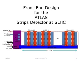
Feedthrough/PatchPanel Cryostat EndCap Discs Services Beam tube Support Sealed Thermal Enclosure Support Flanges Pixel Assembly LS Assembly SS Assembly SLHC new Inner Detector ~ 40M channels in the Si strip detector, today we have ~ 6M channels. We expect to double the Pixel detector from 80M to ~160M ATLAS & SLHC
Fluences at larger radii dominated by neutron-albedo, largest near endcaps. Fluences at small radii dominated by particles from interaction point. Neutron fluence calculation in the ID@SLHC ATLAS & SLHC
Strategy adopted • In the Calorimeter gap region rad-hard front end electronics, minimize opening gap, maximize absorbtion length (shielding plugs). Choose LAr techniques because intrinsically radhard • The present Fe beam pipe and the various bellow/ion pump represent a major problem in term of radiation and activation. Already to go to the design luminosity we will need a lighter beam pipe • In general, minimize the amount of material in front of the forward calorimeters to avoid flooding the entire end-cap calorimeter with back splashes and early showers • at 10**35, we will need to worry about the energy deposition in the liquid to avoid boiling effects in the forward calorimeter. Many investigations are ongoing. This is a major issue to solve! • at 10**35, we will need new front end LAr electronics, the present one will be degraded • at 10**35, we will need to worry about the induced activation of heavy isotopes inside the liquid Argon. We will know better when we turn on the LHC where and how such isotopes moves within an argon cell. ATLAS & SLHC
Hole in front of the Forward Calorimeter ATLAS & SLHC
JM Shielding ATLAS & SLHC
Possibility A : use JM space • Volume available : Rmax= 180 mm, Length= 1090 mm • Zmin=3490 mm, Zmax=4580 mm • All services will run on the front of the calorimeter -> space limited and in competition with the ID services. It took years to ATLAS to optimize this region (barrel GAP) ! • This volume moves with the calorimeter end-cap during access periods (access to the calorimeters and inner detector), all services must go on a flexible chain or must be disconnected! • When we move the calorimeter (1200 tons, 9m diameter), it might be so that it will not go back exactly to the original position (+- 3 mm). Is that a problem? • We need to minimize all material in this region to avoid activation effects and spoiling the performance of the calorimeters, material at big radius preferencially. Today we have about 75 Kg of moderator and 15-20 kg of pipe + services (pump,…) • If too much material, then we have to instrument it as a forward calorimeter (fibers,D0 instrumented) -> very complex project, but we might to do it in any case if we have a LAr boiling problem • A first calculation was done by ATLAS on the effect of important masses of Fe or Cu at this location, on the fluences of neutrons in the inner detector volume. Changes with and without are of a factor 2! • The beam pipe and the associate vacuum system in this region must be fully re-engineered. We need in any case to move to a lighter pipe and remove the existing Ion pump • In this region we will have 1-0.5 Tesla from the central solenoid. Maximum at small z, 0.4T near to the ion pump ATLAS & SLHC
av18 with Fe mass ~2.7 ~2.0 Factor ~2.7 increase due mainly to increase in neutron albedo. Neutron fluence calculation in the ID@SLHC No strong effect propagated to the muon spectrometer, but we need to investigate further. 20% effect on top using Cu instead of Fe, as expected, somewhat more albedo neutrons ATLAS & SLHC
Strategy adopted • For the Muon Spectrometer, the strategy has been to maximize the shielding element all along the beam pipe • All transition regions between one detector component and the next one are generating an increase of ionization radiation in the entire detector volume • Signals in the detectors from background particles are the main issue because it will reduce the tracking efficiency and introduce a large rate of fake triggers ATLAS & SLHC
Disk shielding plug ATLAS & SLHC
JD Shielding + Small muon wheel ATLAS & SLHC
Possibility B : use the JD plug space • Volume available for a magnet: Rmax= 430 mm, Length= 1860 mm • Zmin=6800 mm, Zmax=8660 mm • All services will run on the shield disk -> space limited and in competition with the small wheel chamber. • This volume moves with the JD end-cap during access periods (access to the calorimeters and inner detector +- 2m), all services must go on a flexible chain or must be disconnected! • The JD is not a very stable object (130 tons, 9m diameter), with a center of gravity defined by the weight of the material inside the main tube and the weight of the small wheel. Movements are complicated. • When we move the JD + SW (130 tons, 9m diameter), it might be so that it will not go back exactly to the original position (+- 3 mm). Is that a problem? • We need to maximize all material in this region to avoid spoiling the performance of the muon forward detector, small wheel and barrel ends. Today we have 5.4 tons of SS cylinder + 8.3 tons of brass plugs. This amount is marginal, from the point of view of shielding at 10**34. At 10**35 we will have a problem in any case. We might need to use different active detector technologies there. • The beam pipe in this region must be fully re-engineered. The stay clear radius between 130 and 170 might have to be revisited • About ~30% of the plug is placed inside the end-cap toroid inner bore. ATLAS & SLHC
Endcap toroid shielding ATLAS & SLHC
JTT shielding plug ATLAS & SLHC
Possibility C : use end-cap toroid bore • Volume available for a magnet: Rmax= 870 mm, Length= 4180 mm • Zmin=8690 mm, Zmax=12870 mm • All services will run on the toroid cryostat walls • This volume moves with the Toroid end-caps during access periods (access to the calorimeters and inner detector + 5,12m), all services must go on a flexible chain or must be disconnected! • Well placed in the core of the toroids (~310 tons, 10m diameter). Movements are complicated. • When we move the toroids, it might be so that it will not go back exactly to the original position (+- 3 mm). Is that a problem? • We need to maximize all material in this region to avoid spoiling the performance of the forward muon spectrometer. Today we have 55.2 tons of cast iron on each side + 1.3 tons of cladding. We will have in any case a problem at 10**35. We might need to use different active detector technologies in that region. • The beam pipe in this region must be fully re-engineered. The stay clear radius of 170 to 240 mm might have to be revisited • Everything is placed inside the end-cap toroid inner bore, a field less region in principle! ATLAS & SLHC
Forward Shielding ATLAS & SLHC
JF Forward Shielding ATLAS & SLHC
Possibility D : use JF space • We might want in first place to rebuild a new JF and reorganize the layour in that region • Volume available for a magnet if we keep the existing JF: Rmax= 1500 mm, Length= 5650 mm • Zmin=12950 mm, Zmax=18600 mm • Services routing to be optimized, many possible solutions • This volume will have to be fully dismounted when we open every year ATLAS, because we have to retract the end-cap toroid in that region. Today we can just allow the beam pipe to stay in place. • The JF is very complex, the central core sits in the main barrel rails (via A frame) and on the back directly on the JN. The Octagonal part is support from below independently. The total weight amount to 426 tons of material. • We need to maximize all material in this region to avoid spoiling the performance of the muon forward detector. Today we have 418 tons of ductile iron and 5.5 tons of fancy cladding. The Octagonal section can be extended towards IP by about 2.2 m. This is already in our staging plans. • No way to imagine touching mechanically the big wheels, it would mean take a part and restart a project of many years. • The beam pipe in this region must be fully re-engineered. The stay clear radius between 280 and 450 mm might have to be revisited • The B field from the toroids in this region should be minimal ATLAS & SLHC
JF /JN region final layout (today) ATLAS & SLHC
JF /JN region final layout (baseline) ATLAS & SLHC
JF /JN region final layout (baseline) ATLAS & SLHC
JF /JN region final layout (staged) ATLAS & SLHC
JF /JN region layout (future?) Might be this could become a piece of the machine fully retractable inside th tunnel, when we need to move ATLAS (+5 m) ATLAS & SLHC
Summary: Possible locations we were discussing A B C D • All are possible … but at some cost … our advice: • stay out of A, if it is not strictly necessary • B,C possible location of D0, but we need more calculations to avoid to damage the muon system • D possible location of Q0 or D0, probably the least problematic one • A new TAS can just be studied in the last 2m of JF, very difficult elsewhere ATLAS & SLHC