The SLHC
The SLHC. Université de Genève. Journée de réflexion du DPNC. Centre de rencontre de Cartigny D. Ferrère, 14 septembre 2007. Team: G. Barbier, A. Clark, D. Ferrère, D. Lamarra, S. Pernecke, E. Perrin, M. Pohl. Cartigny, le 14 Septembre 2007 SLHC, Didier 1.

The SLHC
E N D
Presentation Transcript
The SLHC Université de Genève Journée de réflexion du DPNC Centre de rencontre de Cartigny D. Ferrère, 14 septembre 2007 Team: G. Barbier, A. Clark, D. Ferrère, D. Lamarra, S. Pernecke, E. Perrin, M. Pohl Cartigny, le 14 Septembre 2007 SLHC, Didier 1
The European Strategy for Particle Physics Draft Strategy Document Initiatives: http://council-strategygroup.web.cern.ch/council-strategygroup/ “The LHC will be the energy frontier machine for the foreseeable future, maintaining European leadership in the field; the highest priority is to fully exploit the physics potential of the LHC, resources for completion of the initial program have to be secured such that machine and experiments can operate optimally at their design performance. A subsequent major luminosity upgrade (SLHC), motivated by physics results and operation experience, will be enabled by focused R&D; to this end, R&D for machine and detectors has to be vigorously pursued now and centrally organized towards a luminosity upgrade by around 2015.” • SLHC status: • R&D towards a realistic Upgrade scenario is active (Machine and Detectors) • SLHC is not approved yet! • Exact time schedule is unknown • Machine scenarios exist but not frozen Cartigny, le 14 Septembre 2007 SLHC, Didier 2
The ATLAS ID current status at LHC • All services (pipes, cables, fibers,..) Installed • TRT barrel & Endcap cabled and connected - 1.8% problematic channels out of 105K, noise figure as on surface – Cosmics collected in M4 runs • SCT barrel and Endcap signed off on surface - < 0.3% problematic channels out of 6.3 M, >99% efficiency on cosmics. Commissioning in Progress, ongoing delays due to cooling and environmental gas. • Pixel signed off on surface and installed and waiting for connection and tests … towards the end … December 07: End of the ATLAS Installation Jan-Feb 08: Overall ATLAS commissioning March/April 08: Close Access Cartigny, le 14 Septembre 2007 SLHC, Didier 3
Machine and Scenarios 3 phases considered: Phase 0: Push the machine to its maximum performance without hardware change Luminosity of 2.3x1034 cm-2s-1. and ultimate energy 7.54 TeV (dipole field @ 9T) Phase 1 (SLHC): Interaction Region (IR) quadrupoles life expectancy < 10 years Modify the insertion quadrupoles and their layout b* Phase 2: Rebuild the SPS with superconducting magnets, the transfer line to inject into LHC at 1 TeV and new 15T dipoles proton energy of 12.5 TeV Far future Baseline Alternative NB: Original scenario of 12.5 ns excluded since exceed the max local cooling capacity Cartigny, le 14 Septembre 2007 SLHC, Didier 4
Luminosity should be 10 times higher & Upgrade is considered for the detectors Physics Benchmarks Ideally it is desired to increase the luminosity and get a better detector performance • The future observations at LHC should drive physics investigations at SLHC • Higgs: • H couplings to bosons and fermions • WW scattering and resonances • SUSY spectroscopy: • mass reconstruction, sparticle ID, BR measurements, … • performances for heavy SUSY (> 2 TeV) – impact and statistics • EW physics: • Boson self-couplings: focus on those for which the sensitivity is close to ILC • Super-heavy stuff: • Multi-TeV region: light Higgs decay to new gauge bosons Z’, W’ Cartigny, le 14 Septembre 2007 SLHC, Didier 5
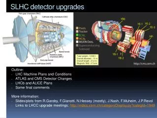
ATLAS Upgrade Due to increase of radiation level, pile-up, background each sub-detectors has to think of the consequences in term of detector performance, aging, radiation hardness! Inner Detector (ID): Completely new design and detectors – No TRT, more pixel and strips: New detector and ASICs technologies to withstand the radiation level Simulations drive optimal geometry (Strawman layers) and occupancies Focus LAr Calorimeter: FCAL: To be replaced with smaller gap size and special cooling close to the beam pipe. HEC: Cold electronics may have to be replaced (no need to get HEC wheels apart) Others: More R&D require about the Ion buid-up Tile Calorimeter: Front-end electronics and Low Voltage Power Supplies Muon System: MDT: Chambers and readout electronics are radhard at LHC or can stand 10 times the max nominal flux but further studies need to be performed in SLHC environment 2008: detail upgrade plan based on some tests and R&D TGC: Thick GEMs can possibly replace forward chambers due to high occupancy. Cartigny, le 14 Septembre 2007 SLHC, Didier 6
Radiation Background in ATLAS at SLHC Simulation using FLUKA2006 • With safety factor of two, design short microstrip layers to withstand 1015neq/cm2 (50% neutrons) • Outer layers up to 4×10¹⁴neq/cm2(and mostly neutrons) Issues • Thermal management and shot noise. Silicon looks to need to be at ~ -25oC (Thermal runaway). Si power: 1W @ -20°C 4W @ -10°C 10W @ 0°C High levels of activation will require careful consideration for access and maintenance. 1 MeV equivalent neutron fluences assuming an integrated luminosity of 3000fb-1 and 5cm of moderator lining the calorimeters (reduces fluences by ~25%) Cartigny, le 14 Septembre 2007 SLHC, Didier 7
Inner Detector Upgrade - Layout The goal for b-layer replacement is fall 2012 Actual b-layer is expected to survive 3 years at LHC design luminosity (~300fb-1) The Upgrade of the entire tracker should take place in 2016 Cartigny, le 14 Septembre 2007 SLHC, Didier 8
Pixel b-layer: 3D technology is an option (should be ready for b-layer replacement in 20012) Exist in single and double column type ionizing particle n+-columns p-Si electrons swept away by transversal field holes drift in central region and diffuse towards p+ contact Silicon Sensors Choice of adequate material thanks to RD50 collaboration Pixel and Strips: n-in-p (planar technology) • No type inversion, full depletion is on structured side • Collection of electrons (faster than p-in-n) Still ~15000e- at 1.1015 cm-2s-1 (FZ or MCZ) 3D FZ 235mm P-FZ 280mm Cartigny, le 14 Septembre 2007 SLHC, Didier 9
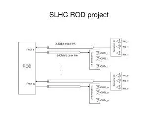
ABC-N Readout architecture • Daniel La Marra, Sebastien Pernecker, Geneva University • Wladek Dabrowski, Krzysztof Swientek, AGH-Cracow • Jan Kaplon, Karolina Poltorak, Francis Anghinolfi, CERN • Mitch Newcomer, Pennsylvania University Design team: Electronics for Strips Goal: Prepare a design of the FE ASIC in deep submicron radiation tolerant. Design and evaluation with 250 nm towards 130 nm technology Minimum requirements: • Implementation of an on-chip shunt regulation to allow any powering scheme (Serial or DC-DC) • Increased data bandwidth of 160 Mb/s • Compatibility with existing ATLAS SCT DAQ ROD hardware • Front-end for two signal polarities, 3 to 12 cm long silicon strips • Minimum power circuit techniques • Delay adjustment for control and data signals • Similar “core” functionality as for the present silicon strip tracker: signal amplification, discriminator, binary data storage for L1 latency, readout buffer with compression logic, and data serializer. Cartigny, le 14 Septembre 2007 SLHC, Didier 10
Module #1 Module #2 Module #10 Cooling TTC, Data & DCS fibers Opto BGT DCS interlock DCS env. IN Service bus SMC PS cable Module Integration Focus on the most challenging modules with Short-Strips, 80 chips (24W), 4 hybrids, 160MHz clocking to FE chips, and readout by group of 10 modules. 3 flavors are considered: Staves, Super-Modules, Modules Cartigny, le 14 Septembre 2007 SLHC, Didier 11
Power Distribution Services are clearly an issue for the material budget as well as for the system design Tracker Upgrade should leave with the existing ID services and optimize the power distribution: Serial Powering or DC-DC (Individual Powering is abandoned) SCT - 4mW/ch 24 kW (excl. cable losses) Strip Upgrade - 2mW/ch 90 kW only for FE (45 Mch) Short-Strip Super-Module configuration n is hybrid number = 20; VH (0.13mm)=1.2V SP IPS=IH=4.2A VPS=nVABCN=24V PP g=GAINDC-DC=20 IPS=n/g.IH=2A VPS=gVABCN=24 V 1 2 3 4 5 6 n-1 n NB: Here only 2 cables/SM needed but for IP it would be 40 cables Cartigny, le 14 Septembre 2007 SLHC, Didier 12
Cooling Cooling System is one of the key points for ID operation Heat density is 4-7 times higher than the current SCT module Detector thermal runaway impose to operate the silicon wafer below -20ºC Tsensor = Tcoolant + DTHeat_Path • Coolant: Less than -30 C is considered for the pipe temperature • Module design and choice of material is critical – Thermal FEA • 3 candidates for the cooling: • CO2 (~100 bar) • C2F6 (Low pressure) • C3F8 (Low pressure) Pressure [bar] • Existing pipes are considered: • SCT & Pixel (ok for C2F6, C3F8) • TRT (ok for CO2 but limited number) 1g of evaporation @ -30ºC ~280 J (Where for C3F8 it is 100 J/g) CO2 Enthalpy [kJ/kg] Cartigny, le 14 Septembre 2007 SLHC, Didier 13
Status in the various working groups • Pixel: • 3D sensors: • ATLAS geometry evaluated: Laser and capacitance measurements • proton and neutron irradiations will soon come • H8 TB will be in September/October 2007 • Readout chips: Prototyping activity in 0.13 mm technology – chip FE 14 • Powering: Promising results for SP – Using current ATLAS Pixel modules • Strips: • Sensors: 10X10 cm2 short strip sensors ordered (15 units for UniGe) • Readout chips ABC-n: Specification document created and under design. The submission is foreseen at the beginning of 2008 • Powering: Promising results for SP – Using current ATLAS SCT modules on • staves and with individual modules. DC-DC is also investigated! • Module Integration: • Concept proposed and some Thermal FEA showed • Prototypes with ABC-n and new n-in-p sensors in 2008 • TB and irradiation will follow • Structure and Services: On going discussions and specifications expected soon Cartigny, le 14 Septembre 2007 SLHC, Didier 14
UniGe Involvements Asics: Digital Architecture & Simulation: pipeline, Derandomizer, Data Compression Logic, Readout Logic and Control; Check after place and route! 250nm submission January 2008 130nm design from January 2008 Detectors: 135 sensors of size10X10cm2 ordered to Hamamatsu UniGe ordered 15 sensors: 12 p-stop and 3 p-spray Sensor characterization will be made and compared with other institutes • Module Concept: UniGe investigated 2 concepts module directly mounted on barrel or mounted on an intermediate local support! • UniGe operates 3D Thermal FEA to evaluate and optimize the design • Strategy is to make prototype modules in 2008 with above detectors and Asics DCS: Involvement in the strategy and decision for the detector safety. DCS will be part of the system design to optimize the service and resource issues. Mechanical Engineering: Involvement in the structure and service design. Cartigny, le 14 Septembre 2007 SLHC, Didier 15
Important Milestones Drafted • Beam off – start decommissioning 1/7/2014 (18 month for installation) • Ready for beam: 1/1/2016 • Straw man Layout -December 2006 (Modification/changes to be made in term of performance /Risk/Cost etc.) • TDR -Feb/2010 • Cooling PRRApril/2010 • Mechanical Support Design completeOct/2010 • Sensor PRRJuly/2010 • FE-electronicsSept/2010 • Surface AssemblyMarch/2012 B-Layer replacement • Ready for InstallationAugust/2014 • Barrel InstallationFeb/2015 • B-layer/beam pipeAugust/2015 Conceptual Design R&D Prototypes Pre-Series Production Assembly & Installation Cartigny, le 14 Septembre 2007 SLHC, Didier 16
Conclusions • SLHC is clearly in the continuity of the machine and detector operation • Phase 1 will be to increase the luminosity up to a factor 10 (1035 cm-2s-1 ) • ATLAS and CMS are considering options to Upgrade the detectors in 2016 • The ATLAS Inner Tracker will be completely renewed (no TRT) and is in a design and specification phase • The B-layer replacement is foreseen already in 2012 using 3-D sensors • The major challenges are: Service and material reductions, Cooling, Powering scheme • The time scale is short and there is almost no time for R&D • Working groups start smoothly to grow and to be active • UniGe involved in various topics and keep an eye on the B-layer replacement activities • Next events: • Pixel Upgrade Workshop 28-29 September at CERN • ID Upgrade Workshop 12-14 Dec 2007in Valencia Cartigny, le 14 Septembre 2007 SLHC, Didier 17
Back-up slides Cartigny, le 14 Septembre 2007 SLHC, Didier 18
Appendix - Tracker Organizational Structure Cartigny, le 14 Septembre 2007 SLHC, Didier 19
new upgrade bunch structures nominal 25 ns new alternative! ultimate & 25-ns upgrade 25 ns 50-ns upgrade, no collisions @S-LHCb! new baseline! 50 ns 50-ns upgrade with 25-ns collisions in LHCb 50 ns 25 ns Cartigny, D. Ferrere
Two scenarios Luminosity Upgrade Cartigny, D. Ferrere
Per Grafstrom CERN Heat load Cartigny, D. Ferrere
B-Layer Replacement Cartigny, D. Ferrere
B-Layer Replacement & Tracker Upgrade • ATLAS considers to have a B-layer replacement after ~3 year of integrated full LHC luminosity (2012) and replace completely the Inner Tracker with a fully silicon version for SLHC (2016). • The B-layer replacement can be seen as an intermediate step towards the full upgrade. Performance improvements for the detector (here some issues more related to FE chip): • Reduce radius and design for > 1034cm-2s-1 luminosity Improve radiation hardness ( 3D sensor, p-type bulk materials) • Reduce pixel cell and architecture related dead time ( deign FE for higher luminosity) • Reduce material budget of the b-layer (~3% X0 <2.5% X0) stave replaces module as the basic building block. • increase the module live fraction ( increase chip size, > 1214 mm2), optimize inactive chip periphery, use “active edge” technology in the sensor. • Use faster R/O links, move MCC at the end of stave • FE chip technology will use 0.13 µm 8 metal CMOS. • The B-layer for the upgrade will push even more technological/ design/ architectural issues of the FE chip radiation hardness (1015 1016 neq/cm2) and detector occupancies ( 15) Cartigny, D. Ferrere
LSR on Barrel (UniGe Concept) Reference (r, Z) + fixation Intermediate support bracket + insertion guide 10-Module Structure Half barrel Barrel end Reference (r,f) + alignment End view Cartigny, D. Ferrere
EC disks – Petal option C. Lacasta SS disks SS+LS disks Cartigny, D. Ferrere
Data Transmission Cartigny, D. Ferrere
Low evaporation pressure limit • Limit from return line impedance and compressor suction pressure. • Mostly of concern for C3F8 • TRT pipes would give ~70% more flow → return pipe Δp would have to increase (α ~P2), • Heaters/HEXs (diameter) need to be bigger, • Alternative pev control: cold condenser (needs development), • Surface condensers to reduce compression ratio → allows to reduce suction p. • Mix with C2F6: • Allows to tailor saturation properties, • Lower HTC to wall (~50%), • Mixture control by measurement of vsound. Cartigny, D. Ferrere
Coolant properties Run conditions @ -35C Major difference for CO2 with respect to C3F8 cooling is the increase by a factor of 10 of the evaporation pressure for T=-35C. Advantages…. Cartigny, D. Ferrere