Autonomous Quad-Rotor Project:
170 likes | 312 Views
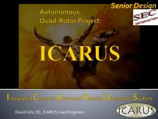
Senior Design. David Gitz, EE, ICARUS Lead Engineer. ICARUS. Autonomous Quad-Rotor Project:. I ntegrated C omplex A dvanced R obotic U nmanned S ystem. Topics:. System Description Capabilities and Technologies System Specifications Senior Design Proposals. System Description.

Autonomous Quad-Rotor Project:
E N D
Presentation Transcript
Senior Design David Gitz, EE, ICARUS Lead Engineer ICARUS AutonomousQuad-Rotor Project: Integrated Complex Advanced Robotic Unmanned System
Topics: System Description Capabilities and Technologies System Specifications Senior Design Proposals
Vehicle • Quad-Rotor design – Offers simpler control system with fewer moving parts than a single rotor helicopter and minor reduction in lift capacity
Vehicle Specifications • Sensors: 3-Axis Accelerometer, 3-Axis Gyroscope, 3-Axis Magnetometer (INU), Digital Compass, Altimeter, GPS, 7 Ultrasonic Sensors • Power: 8 Brushless DC 200 Watt Motors, 4 Micro Servo’s, 2 Lithium-Ion 11.1V 5 Amp-Hours Batteries, 4 18A Electronic Speed Controllers, 5V and 3.3V Linear Voltage Regulators. • Control: SoM Controller (Primary), Propeller Controller (Secondary), custom PCB. • Communications: Xbee Radio for Command/Control, Video Transmitter, Wi-Fi. • Fabrication: ~50% COTS, ~50% produced by MakerBot/Ponoku.
RCU • Custom PCB inside Xbox-360 Controller • Features Mode and Error Display, Vehicle Battery Indicator, Force-Feedback and 5 hours of continuous operation.
GCS • Includes computer, touch-screen monitor and batteries for field operation. • Communications Radio and Video Receiver • Heavy-duty field transportable case
GCS Interface • Manual Control • Vehicle Sensor Display • Vehicle Health/Feedback System • Autonomous Control • Set, Transmit Waypoints • Communications • View Network Status • Configuration/Debugging • Google Earth Integration • Fully controllable Google Earth (location search, zoom, pan, etc). • View Waypoints and Vehicle Location/Path
Test-Stand • Used for Vehicle Calibration and Capacity measurements • Able to Pivot vertically, rotate continuously and pitch/yaw/roll on Test-Fixture Assembly • Power applied to Vehicle via Slip-Ring – No tangled wires
InmarSat Satellite GPS Satellite Command/Control Video GPS Services Diagram Vehicle WAN Cellular Network Ground Entry Point RCU GCS
System Specifications • Range: ~1.5 km LOS (~3km with Xbee Mesh Network) • Duration: • Vehicle: ~12 min (100% Throttle) , ~20 min (Hover) • RCU: ~4-6 hrs • GCS: ~4-6 hrs (including field charging Vehicle) • Speed: ~2 - 4 kph • Weight: ~5.5 lbs • Size: 48” x 48” x 10.5” • Propeller Rotation: Max: 3,000 RPM • Vertical Thrust: ~7.8 lbs
Senior Design Proposals Automatic Landing Pad Aerodynamic Analysis Swarm Autonomy Control System Design
Questions? • Contact: • David Gitz: david.gitz@icarusuav.com • Ben Wasson: ben.wasson@icarusuav.com