Download
1 / 19
190 likes | 416 Views
A basic introduction to Molten Silicate electrolysis. Different Oxygen extraction methods were considered: . A basic introduction to Molten Silicate electrolysis. Molten silicate (SiO2) electrolysis advantages over the other reactions:

E N D
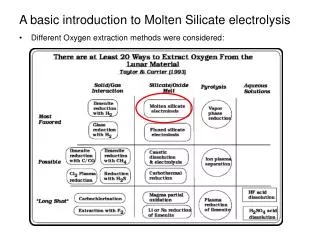
A basic introduction to Molten Silicate electrolysis • Different Oxygen extraction methods were considered:
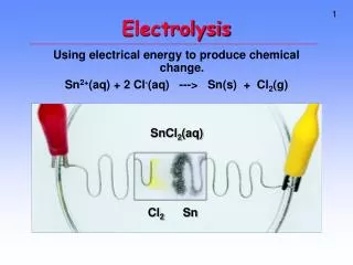
A basic introduction to Molten Silicate electrolysis • Molten silicate (SiO2) electrolysis advantages over the other reactions: • normal reducing agents not available on the moon => electrolysis • high concentration of silicates in the lunar regolith (~45%) • relatively high efficiency • ease of separation of oxygen (just melt it, and then electrolyze it!) • Disadvantages: • high temperatures and high power required for reaction to take place
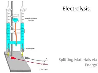
A closer (more detailed) look to the reaction Cathode Reactions: Anode Reaction: Reaction T: ~1400-1450°C Reaction P: Lunar atmosphere => vacuum
Original procedure outline • Sifting: Get rid of massive chunks of regolith. • Conductivity separation chamber: Use of this separation technique has been reconsidered –looking into spectroscopy instead. • Reaction chamber • Oxygen Separation • Oxygen Analyzer: For analysis purposes. • Oxygen collection chamber: Compress and store produced oxygen.
A. Sifting chamber • The idea behind it: To get rid of massive chunks of regolith: We have feed-thru’s with small cross sections; we don’t want big chunks to get stuck in them and clog them Also considering variation of mineral consentration vs. grain size that could potentially affect our process efficiency ? Big chunks take longer to melt, use up too much power; might not even end up melting during our reaction procedure
B. Conductivity separation chamber • Initially, the idea behind it: We only wanted to heat up soil that will give us O2. Energy should not be used up in heating up soil that will not melt or electrolyze, since it will not serve the purpose of oxygen extraction. The process required heating soil to ~700°C to increase conductivity Due to heating, gases – mostly H2, H2O, CF4 (from solar wind, etc) that are in lunar soil are liberated) • However: !After investigatingconductivities for silicates and O2-rich substances on the moon, we concluded that this process will not cause any considerable increase in overall O2 production efficiency Alternative method
B. Alternative method to Conductivity separation:Soil Spectroscopy • The idea behind it O2-rich substances on the moon that melt within a lower temperature range (1400-1450C) and efficiently give out oxygen, can be identified by the wavelengths they reflect when undergoing spectroscopy. These wavelengths are differentiated enough between different substances, and the substances are scattered on the moon surface in such a way that they allow for spectroscopy to be used for selectively acquiring the right type of soil for our process. • The process Will require a spectroscope attached to the mechanical arm which will scan lunar soil and identify regions with desired type of soil Through a controller, the mechanical arm will only be allowed to pick up that soil that is desired for greater efficiency
C. Reaction chamber This is where the reaction takes place! I.e., where the soil (mainly silicates) is heated up to melting point, and then electrolysis occurs, giving out oxygen… Remember: T = ~1400-1450C P = vacuum Also, at this point we want to be able to get rid of all the processed material, after the reaction is completed… (Waste disposal, which is what the valve is for)
C. Initial Reaction chamber setup Most probable heating element materials: tungsten Also changing the geometry to coil
C. Reaction chamber - Electrodes • The idea behind it: We used the cylindrical shape (cathode surrounds anode) to allow collecting the O2 that is produced on the anode and transferring it outside the chamber Initial setup Electrodes embedded throughout the whole volume of the fluid Possible anodes considered: Iridium or Pt Possible cathodes considered: C or Pt with Fe-Si coating Modified (new) setup: More surface area (total) Only one opening for heat to escape Can afford losing one electrode to clogging No need for stirring viscous fluid Problems we are facing: Accumulation of Si, and formation of Si-Pt alloy on cathode, which could potentially clog/destroy the electrode
C. Reaction chamber – Electrodes (new setup) Modified (new) setup: More surface area (total) Only one opening for heat to escape Can afford losing one electrode to clogging No need for stirring viscous fluid Electrodes embedded throughout the whole volume of the fluid
C. Reaction chamber – Insulation – initial design • The idea behind it: Heat loss prevents from reaching the temperature we need for reaction to take place. Since we have power limits, we need to save as much heat as we can Heat loss is both due to conduction and radiation (Radiated heat ~ σT4) Initial design (on the left) has been reconsidered New design: more radiation shielding
C. Reaction chamber – Insulation – new design New design: more radiation shielding, more vacuum, less solid contact Possible container materials: Tantalum, or Molybdenum* *Mo forms an oxide that evaporates easily Possible reflective layers: Al, Au, Ag, or Pt Possible insulator materials: Alumina (Al2O3), or Zirconia (ZO2) stabilized with Yttria (Y2O3)
D. Oxygen separation chamber • The idea behind it: Along with O2, other gases could potentially escape our reaction chamber… Our goal is to extract O2, so we have to separate those gases out The diagram on the left depicts an O2 separator; it uses membranes that are selectively permeable to O2; works with low-P gas and T=~700C Cerametic Inc. Ion Transport Membrane Cost: $10,000
E. Gas analyzers/O2 sensor • The idea behind it: After we separate the O2, we want to see what efficiency we have by looking at purity of O2 If we know volume, we can calculate the % O2 produced Also, we can see if any O2 is lost in previous stages
F. Oxygen collecting chamber • The idea behind it: Condense O2 by cooling it down and store it … or compress it (use small, efficient compressor). Haven’t started working on it yet!!!!
A few more notes… The valves that we are using for our reaction chamber for disposal have to be able to withstand the temperature of the molten silicates, as well as be non-corrosive to them. The valves that we are using for our reaction chamber for O2 transfer have to be able to withstand the temperature of the O2 gas, as well as be non-corrosive to it. For cooling mechanism, we will try to find a low P, low m compressor.
If you have any questions, send an EMAIL to: gkaragio@fit.edu