Digital COMMUNICATION
Digital COMMUNICATION. SWAPNIL UPADHYAY. Scope of digital communication. Internet Mobile Networks Wireless Networks. Our interest. Arduino Shields. Use SPI or UART to communicate with arduino boards . JPG Color Camera. Uses UART to communicate with Master board.


Digital COMMUNICATION
E N D
Presentation Transcript
DigitalCOMMUNICATION SWAPNIL UPADHYAY
Scope of digital communication Internet Mobile Networks Wireless Networks
Arduino Shields Use SPI or UART to communicate with arduino boards
JPG Color Camera Uses UART to communicate with Master board
Accelerometers Communication through SPI
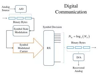
Essentials of Communication But this simple model requires many guarantees. Sender Communication Link Receiver Data
Guarantees in Communications • The communication link exists. • The communication link is sound. • The sender and receiver are the correct nodes. • The sender is sending the correct data. • The receiver is able to correctly interpret the incoming data.
Protocols in Communication • In order to have robust communication, the guarantees needs to be realized. • To do so, we need an elaborate and standardized mechanism. • These standard rules that defines the parameters of communications and ensures these guarantees are called protocol.
Advantages of Protocols • Standardized, so interoperability is ensured. • Usually include error-detection and error-correction mechanisms. • Are available as implemented chips that can be directly used.
Types of Protocols • There are different ways of categorizing protocols • First Categorization : • Second Categorization : Serial Mode Transfer Parallel Mode Transfer Synchronous Mode Transfer Asynchronous Mode Transfer
Serial and Parallel Mode SENDER SENDER RECIEVER RECEIVER PARALLEL MODE SERIAL MODE
Serial Vs Parallel Mode Parameter Reliability Speed Power Cost Complexity Range Serial Mode Parallel Mode Reliable Unreliable Slow Fast Low High Low High High Low Long Short
Synchronous transmission • Sender sends a clock signal along with data at every rising / falling edge of the clock, the data value is read by the receiver. SENDER 1 0 1 0 SENDER CLOCK 0 1 0 1 RECIEVER
Need of Synchronization T T 1 1 1 1 1 1 SENDER 0 0 0 0 0 0 Suppose Sender sends data with a Time Period of T What if Receiver doesn’t know the speed and assume it to be say T/2 The Data received will be
Asynchronous Mode • There is no clock signal. • The receiver and the sender communicate at a predetermined speed (bauds or bits per second). • Baud Rate : Baud Rate is a measurement of transmission speed in asynchronous communication. The devices that allows communication must all agree on a single speed of information - 'bits per second'.
Transmission Modes SENDER RECIEVER Simplex Only one way transmission takes place
Transmission Modes SENDER RECIEVER Half-Duplex Two way transmission takes place but only one end can communicate at a time
Transmission Modes SENDER RECIEVER Full-Duplex Two way transmission takes place and both end can communicate simultaneously
UART • UART is a simple half-duplex, asynchronous, serial protocol. • Simple communication between two equivalent nodes. • Any node can initiate communication. • Since connection is half-duplex, the two lanes of communication are completely independent.
Connections for uart Tx Rx Gnd Rx Tx Gnd Device 1 Device 2
Connections for uart Tx Rx Gnd Rx Tx Gnd Device 1 Device 2
Connections for uart Tx Rx Gnd Rx Tx Gnd Device 1 Device 2
UART Characteristics • The speed of communication (measured in bauds) is predetermined on both ends. • A general rule of thumb is to use 9600 bauds for wired communication. • UART implements error-detection in the form of parity bit.
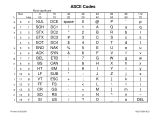
Parity bit • Parity bit is HIGH when number of 1’s in the Data is odd(if bit parity is even). • Respectively, it is LOW when number of 1’s in the Data is even (if parity is even).
SPI • Serial ?? • Because it works on serial mode of transfer. It is also synchronous and full duplex. • Peripheral Interface. • Because it has the capability of communicate with many nodes. • How?? Let us see.
SPI • In SPI, the sender and receiver follows a master-slave relationship. • There may be multiple nodes in the network. • One node is master, the rest are slaves. • The communication is always initiated by the master. • The slaves can communicate only with the master. • How do master selects the slave??
SPI Pins • CLK is generated by Master and is used as the mode is synchronous. • MOSI is Master Out Slave In: Data sent by Master to Slave. • MISO is Master In Slave Out: Data sent by Slave to Master. • S̅S̅ is slave select: Slave communicates with Master only if this pin’s value is set as LOW.
Data Transfer in SPI MOSI MISO MASTER SLAVE
Data Transfer in SPI MOSI MISO MASTER SLAVE
Data Transfer in SPI MOSI MISO MASTER SLAVE
Data Transfer in SPI MOSI MISO MASTER SLAVE
Gps satellites • Total 27 satellites out of 24 works at a time and rest 3 are emergency backup.
Distance calculation • Distance = speed xtime = c x (t2-t1)
trilateration • In geometry, trilateration is the process of determining absolute or relative locations of points by measurement of distances, using the geometry of circles, spheres or triangles.
hyperTerminal • Software to communicate with other devices using com ports.