Download
1 / 29
300 likes | 390 Views
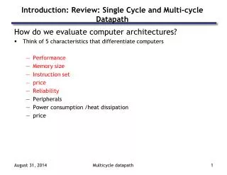
Learn how to optimize a pipelined datapath by breaking it into stages, handling pipeline registers, and managing control signals effectively. Explore the performance and implications of pipelining various instruction types.

E N D
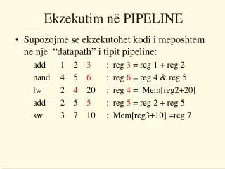
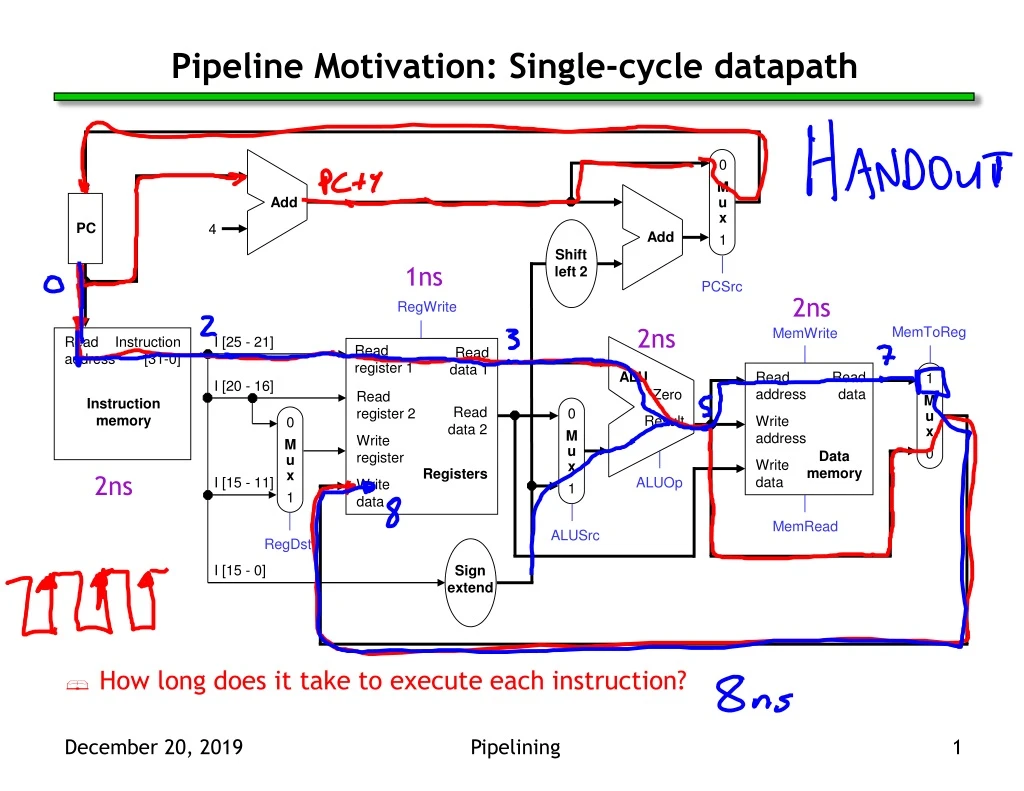
0 M u x 1 Add PC 4 Add Shift left 2 PCSrc RegWrite MemToReg MemWrite Read address Instruction [31-0] I [25 - 21] Read register 1 Read data 1 ALU Read address Read data 1 M u x 0 I [20 - 16] Zero Read register 2 Instruction memory Read data 2 0 M u x 1 Result Write address 0 M u x 1 Write register Data memory Write data Registers I [15 - 11] ALUOp Write data MemRead ALUSrc RegDst I [15 - 0] Sign extend Pipeline Motivation: Single-cycle datapath 1ns 2ns 2ns 2ns • How long does it take to execute each instruction? Pipelining
Break datapath into 5 stages IF WB ID EXE MEM RegWrite MemToReg MemWrite Read address Instruction [31-0] I [25 - 21] Read register 1 Read data 1 ALU Read address Read data 1 M u x 0 I [20 - 16] Zero Read register 2 Instruction memory Read data 2 0 M u x 1 Result Write address 0 M u x 1 Write register Data memory Write data Registers I [15 - 11] ALUOp Write data MemRead ALUSrc RegDst I [15 - 0] Sign extend
How fast can we clock this datapath IF WB ID EXE MEM RegWrite MemToReg MemWrite Read address Instruction [31-0] I [25 - 21] Read register 1 Read data 1 ALU Read address Read data 1 M u x 0 I [20 - 16] Zero Read register 2 Instruction memory Read data 2 0 M u x 1 Result Write address 0 M u x 1 Write register Data memory Write data Registers I [15 - 11] ALUOp Write data MemRead ALUSrc RegDst I [15 - 0] Sign extend 2ns 1ns 2ns 2ns
Pipelining Performance • Execution time on ideal pipeline: • time to fill the pipeline + one cycle per instruction • How long for N instructions? • Compare with other implementations: • Single Cycle: (8ns clock period) • How much faster is pipelining for N=1000 ? filling Pipelining
Pipelining other instruction types • R-type instructions only require 4 stages: IF, ID, EX, and WB • We don’t need the MEM stage • What happens if we try to pipeline loads with R-type instructions? Pipelining
Important Observation • Each functional unit can only be used once per instruction • Each functional unit must be used at the same stage for all instructions: • Load uses Register File’s Write Port during its 5th stage • R-type uses Register File’s Write Port during its 4th stage Pipelining
A solution: Insert NOP stages • Enforce uniformity • Make all instructions take 5 cycles. • Make them have the same stages, in the same order • Some stages will do nothing for some instructions • Stores and Branches have NOP stages, too… Pipelining
Add Add Single-cycle datapath, slightly rearranged 1 0 PCSrc 4 P C Shift left 2 RegWrite Read register 1 Read data 1 MemWrite ALU Read address Instruction [31-0] Zero Read register 2 Read data 2 0 1 Result Address Write register Data memory Instruction memory MemToReg Registers ALUOp Write data ALUSrc Write data Read data 1 0 Instr [15 - 0] Sign extend RegDst MemRead Instr [20 - 16] 0 1 Instr [15 - 11] Pipelined datapath and control
Pipeline registers • We’ll add intermediate registers to our pipelined datapath. • There’s a lot of information to save, however. We’ll simplify our diagrams by drawing just one big pipeline register between each stage. • The registers are named for the stages they connect. IF/ID ID/EX EX/MEM MEM/WB • No register is needed after the WB stage, because after WB the instruction is done. Pipelined datapath and control
0 1 Add Add Shift left 2 Pipelined datapath 1 0 PCSrc 4 IF/ID ID/EX EX/MEM MEM/WB P C RegWrite Read register 1 Read data 1 MemWrite ALU Read address Instruction [31-0] Zero Read register 2 Read data 2 0 1 Result Address Write register Data memory Instruction memory MemToReg Registers ALUOp Write data ALUSrc Write data Read data 1 0 Instr [15 - 0] Sign extend RegDst MemRead Instr [20 - 16] Instr [15 - 11] Pipelined datapath and control
Propagating values forward • Any data values required in later stages must be propagated through the pipeline registers. • The most extreme example is the destination register. • The rd field of the instruction word, retrieved in the first stage (IF), determines the destination register. But that register isn’t updated until the fifth stage (WB). • Thus, the rd field must be passed through all of the pipeline stages, as shown in red on the next slide. • Notice that we can’t keep a single “instruction register,” because the pipelined machine needs to fetch a new instruction every clock cycle. Pipelined datapath and control
Add Add Shift left 2 The destination register 1 0 PCSrc 4 IF/ID ID/EX EX/MEM MEM/WB P C RegWrite Read register 1 Read data 1 MemWrite ALU Read address Instruction [31-0] Zero Read register 2 Read data 2 0 1 Result Address Write register Data memory Instruction memory MemToReg Registers ALUOp Write data ALUSrc Write data Read data 1 0 Instr [15 - 0] Sign extend RegDst MemRead Instr [20 - 16] 0 1 Instr [15 - 11] Pipelined datapath and control
What about control signals? • The control signals are generated in the same way as in the single-cycle processor—after an instruction is fetched, the processor decodes it and produces the appropriate control values. • But just like before, some of the control signals will not be needed until some later stage and clock cycle. • These signals must be propagated through the pipeline until they reach the appropriate stage. We can just pass them in the pipeline registers, along with the other data. • Control signals can be categorized by the pipeline stage that uses them. Pipelined datapath and control
0 1 Add Add Shift left 2 Pipelined datapath and control 1 0 ID/EX EX/MEM WB PCSrc WB Control MEM/WB M 4 IF/ID EX M WB P C RegWrite Read register 1 Read data 1 MemWrite ALU Read address Instruction [31-0] Zero Read register 2 Read data 2 0 1 Result Address Write register Data memory Instruction memory MemToReg Registers ALUOp Write data ALUSrc Write data Read data 1 0 Instr [15 - 0] Sign extend RegDst MemRead Instr [20 - 16] Instr [15 - 11] Pipelined datapath and control
Notes about the diagram • The control signals are grouped together in the pipeline registers, just to make the diagram a little clearer. • Not all of the registers have a write enable signal. • Because the datapath fetches one instruction per cycle, the PC must also be updated on each clock cycle. Including a write enable for the PC would be redundant. • Similarly, the pipeline registers are also written on every cycle, so no explicit write signals are needed. Pipelined datapath and control
An example execution sequence • Here’s a sample sequence of instructions to execute. 1000: lw $8, 4($29) 1004: sub $2, $4, $5 1008: and $9, $10, $11 1012: or $16, $17, $18 1016: add $13, $14, $0 • We’ll make some assumptions, just so we can show actual data values. • Each register contains its number plus 100. For instance, register $8 contains 108, register $29 contains 129, and so forth. • Every data memory location contains 99. • Our pipeline diagrams will follow some conventions. • An X indicates values that aren’t important, like the constant field of an R-type instruction. • Question marks ??? indicate values we don’t know, usually resulting from instructions coming before and after the ones in our example. addresses in decimal Pipelined datapath and control
0 1 1 0 ID/EX EX/MEM WB Add Add PCSrc Control MEM/WB M WB Shift left 2 4 IF/ID EX M WB _____ P C RegWrite (?) ??? ??? ??? Read register 1 Read data 1 1000 MemWrite (?) ALU Read address Instruction [31-0] Zero ??? ??? Read register 2 Read data 2 ??? ??? 0 1 Result Address ??? Write register MemToReg (?) ??? Data memory Instruction memory Registers ALUOp (???) ??? Write data ??? ??? ALUSrc (?) Write data Read data 1 0 Sign extend ??? ??? RegDst (?) ??? MemRead (?) ??? ??? ??? ??? ??? ??? ??? ??? Cycle 1 (filling) IF: lw $8, 4($29) ID: ??? EX: ??? MEM: ??? WB: ??? Pipelined datapath and control
1 0 0 1 ID/EX EX/MEM WB Add Add PCSrc Control MEM/WB M WB Shift left 2 4 IF/ID EX M WB 1008 P C RegWrite (?) ___ rs___ ??? Read register 1 Read data 1 1004 MemWrite (?) ALU Read address Instruction [31-0] Zero rt___ ___ ??? Read register 2 Read data 2 ??? 0 1 Result Address ??? Write register MemToReg (?) rd__ Data memory Instruction memory Registers ALUOp (???) ___ Write data ??? ??? ALUSrc (?) Write data Read data 1 0 Imm____ Sign extend ??? RegDst (?) ??? MemRead (?) rt____ ??? ??? ??? ??? rd____ ??? ??? Cycle 2 IF: sub $2, $4, $5 ID: lw $8, 4($29) EX: ??? MEM: ??? WB: ??? Pipelined datapath and control
0 1 1 0 ID/EX EX/MEM WB Add Add PCSrc Control MEM/WB M WB Shift left 2 4 IF/ID EX M WB 1012 P C RegWrite (?) 104 4 ___ Read register 1 Read data 1 1008 MemWrite (?) ALU Read address Instruction [31-0] Zero 5 __ 105 Read register 2 Read data 2 ??? 0 1 Result Address __ ___ Write register MemToReg (?) ??? Data memory Instruction memory Registers ALUOp (___) ??? Write data ??? ??? ALUSrc (___) Write data Read data 1 0 X Sign extend __ RegDst (___) MemRead (?) ??? X __ ??? ??? ___ 2 __ ??? Cycle 3 IF: and $9, $10, $11 ID: sub $2, $4, $5 EX: lw $8, 4($29) MEM: ??? WB: ??? Pipelined datapath and control
1 0 0 1 ID/EX EX/MEM WB Add Add PCSrc Control MEM/WB M WB Shift left 2 4 IF/ID EX M WB 1016 P C RegWrite (?) 110 10 104 Read register 1 Read data 1 1012 MemWrite (___) ALU Read address Instruction [31-0] Zero 11 105 111 Read register 2 Read data 2 ___ 0 1 Result Address –1 Write register MemToReg (?) ??? Data memory Instruction memory Registers ALUOp (sub) ??? Write data ___ ??? ALUSrc (0) Write data Read data __ 1 0 X Sign extend X RegDst (1) ??? MemRead (___) X X 2 ___ ??? 9 2 ??? Cycle 4 IF: or $16, $17, $18 ID: and $9, $10, $11 EX: sub $2, $4, $5 MEM: lw $8, 4($29) WB: ??? Pipelined datapath and control
1 0 0 1 ID/EX EX/MEM WB Add Add PCSrc Control MEM/WB M WB Shift left 2 4 IF/ID EX M WB 1020 P C RegWrite (___) 117 17 110 Read register 1 Read data 1 1016 MemWrite (0) ALU Read address Instruction [31-0] Zero 18 111 118 Read register 2 Read data 2 -1 0 1 Result Address __ Write register MemToReg (___) 110 Data memory Instruction memory Registers ALUOp (and) __ Write data X ___ ALUSrc (0) Write data Read data 105 1 0 X Sign extend X RegDst (1) ____ MemRead (0) X X 9 2 ___ 16 9 ___ Cycle 5 (full) IF: add $13, $14, $0 ID: or $16, $17, $18 EX: and $9, $10, $11 MEM: sub $2, $4, $5 WB: lw $8, 4($29) Pipelined datapath and control
1 0 0 1 ID/EX EX/MEM WB Add Add PCSrc Control MEM/WB M WB Shift left 2 4 IF/ID EX M WB ??? P C RegWrite (1) 114 14 117 Read register 1 Read data 1 1020 MemWrite (0) ALU Read address Instruction [31-0] Zero 0 118 0 Read register 2 Read data 2 110 0 1 Result Address 119 2 Write register MemToReg (0) Data memory Instruction memory Registers ALUOp (or) -1 Write data X ALUSrc (0) Write data Read data 111 1 0 X Sign extend X RegDst (1) MemRead (0) X X 16 9 13 16 Cycle 6 (emptying) IF: ??? ID: add $13, $14, $0 EX: or $16, $17, $18 MEM: and $9, $10, $11 WB: sub $2, $4, $5 Pipelined datapath and control
1 0 0 1 ID/EX EX/MEM WB Add Add PCSrc Control MEM/WB M WB Shift left 2 4 IF/ID EX M WB ??? P C RegWrite (1) ??? ??? 114 Read register 1 Read data 1 ??? MemWrite (0) ALU Read address Instruction [31-0] Zero ??? 0 ??? Read register 2 Read data 2 119 0 1 Result Address 9 Write register MemToReg (0) 114 Data memory Instruction memory Registers ALUOp (add) 110 Write data X X ALUSrc (0) Write data Read data 118 1 0 ??? Sign extend X RegDst (1) MemRead (0) 110 ??? X 13 16 9 ??? 13 110 Cycle 7 IF: ??? ID: ??? EX: add $13, $14, $0 MEM: or $16, $17, $18 WB: and $9, $10, $11 Pipelined datapath and control
1 0 0 1 ID/EX EX/MEM WB Add Add PCSrc Control MEM/WB M WB Shift left 2 4 IF/ID EX M WB ??? P C RegWrite (1) ??? ??? ??? Read register 1 Read data 1 ??? MemWrite (0) ALU Read address Instruction [31-0] Zero ??? ??? ??? Read register 2 Read data 2 114 0 1 Result Address 16 Write register MemToReg (0) ??? Data memory Instruction memory Registers ALUOp (???) 119 Write data X X ALUSrc (?) Write data Read data 0 1 0 ??? Sign extend ??? RegDst (?) MemRead (0) 119 ??? ??? 13 16 ??? ??? ??? 119 Cycle 8 IF: ??? ID: ??? EX: ??? MEM: add $13, $14, $0 WB: or $16, $17, $18 Pipelined datapath and control
1 0 0 1 ID/EX EX/MEM WB Add Add PCSrc Control MEM/WB M WB Shift left 2 4 IF/ID EX M WB ??? P C RegWrite (1) ??? ??? ??? Read register 1 Read data 1 ??? MemWrite (?) ALU Read address Instruction [31-0] Zero ??? ??? ??? Read register 2 Read data 2 ??? 0 1 Result Address 13 Write register MemToReg (0) ??? Data memory Instruction memory Registers ALUOp (???) 114 Write data X X ALUSrc (?) Write data Read data ? 1 0 ??? Sign extend ??? RegDst (?) 114 MemRead (?) ??? ??? ??? 13 ??? ??? ??? 114 Cycle 9 IF: ??? ID: ??? EX: ??? MEM: ??? WB: add $13, $14, $0 Pipelined datapath and control
That’s a lot of diagrams there • Compare the last nine slides with the pipeline diagram above. • You can see how instruction executions are overlapped. • Each functional unit is used by a different instruction in each cycle. • The pipeline registers save control and data values generated in previous clock cycles for later use. • When the pipeline is full in clock cycle 5, all of the hardware units are utilized. This is the ideal situation, and what makes pipelined processors so fast. • Try to understand this example or the similar one in the book at the end of Section 6.3. Pipelined datapath and control
Summary • The pipelined datapath extends the single-cycle processor that we saw earlier to improve instruction throughput. • Instruction execution is split into several stages. • Multiple instructions flow through the pipeline simultaneously. • Pipeline registers propagate data and control values to later stages. • The MIPS instruction set architecture supports pipelining with uniform instruction formats and simple addressing modes. • Next lecture, we’ll start talking about Hazards. Pipelined datapath and control
0 1 Add Add Shift left 2 Note how everything goes left to right, except … 1 0 PCSrc 4 IF/ID ID/EX EX/MEM MEM/WB P C RegWrite Read register 1 Read data 1 MemWrite ALU Read address Instruction [31-0] Zero Read register 2 Read data 2 0 1 Result Address Write register Data memory Instruction memory MemToReg Registers ALUOp Write data ALUSrc Write data Read data 1 0 Instr [15 - 0] Sign extend RegDst MemRead Instr [20 - 16] Instr [15 - 11] Pipelined datapath and control
1 0 0 1 ID/EX EX/MEM WB Add Add PCSrc Control MEM/WB M WB Shift left 2 4 IF/ID EX M WB ??? P C RegWrite (1) 114 14 117 Read register 1 Read data 1 1020 MemWrite (0) ALU Read address Instruction [31-0] Zero 0 118 0 Read register 2 Read data 2 110 0 1 Result Address 119 2 Write register MemToReg (0) Data memory Instruction memory Registers ALUOp (or) -1 Write data X X ALUSrc (0) Write data Read data 111 1 0 X Sign extend X RegDst (1) -1 MemRead (0) X X 16 9 2 13 16 -1 Cycle 6 (emptying) IF: ??? ID: add $13, $14, $0 EX: or $16, $17, $18 MEM: and $9, $10, $11 WB: sub $2, $4, $5 Pipelined datapath and control