Download
1 / 37
490 likes | 1.14k Views
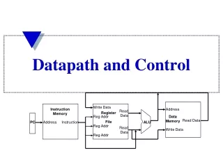
Pipelined Datapath and Control. Lecture for CPSC 5155 Edward Bosworth, Ph.D. Computer Science Department Columbus State University. MIPS Pipelined Datapath. §4.6 Pipelined Datapath and Control. MEM. Right-to-left flow leads to hazards. WB. Pipeline registers.

E N D
Pipelined Datapath and Control Lecture for CPSC 5155 Edward Bosworth, Ph.D. Computer Science Department Columbus State University
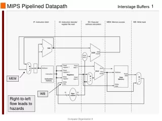
MIPS Pipelined Datapath §4.6 Pipelined Datapath and Control MEM Right-to-left flow leads to hazards WB Chapter 4 — The Processor — 2
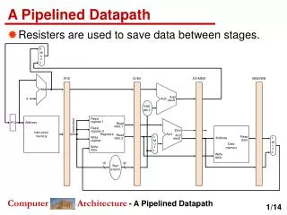
Pipeline registers • Need registers between stages • To hold information produced in previous cycle Chapter 4 — The Processor — 3
The Pipeline Registers • IF/ID This provides an execution context for the ID (Instruction Decode and Register Fetch) stage of execution. • ID/EX This provides an execution context for the EX (Execute) phase of instruction execution. In particular, the discrete control signals generated by the control unit as a result of instruction decoding are stored here. • EX/MEM This provides an execution context for the MEM (Memory Access or R-Type Instruction Completion) phase of instruction execution. In addition , this register stores copies of the control signals required to complete both the MEM and WB phase of execution for this instruction. • MEM/WB This provides an execution context for the WB (Write Back) phase of instruction execution.
Pipeline Operation • Cycle-by-cycle flow of instructions through the pipelined datapath • “Single-clock-cycle” pipeline diagram • Shows pipeline usage in a single cycle • Highlight resources used • c.f. “multi-clock-cycle” diagram • Graph of operation over time • We’ll look at “single-clock-cycle” diagrams for load & store Chapter 4 — The Processor — 5
IF for Load, Store, … Chapter 4 — The Processor — 6
ID for Load, Store, … Chapter 4 — The Processor — 7
EX for Load Chapter 4 — The Processor — 8
MEM for Load Chapter 4 — The Processor — 9
WB for Load Wrongregisternumber Chapter 4 — The Processor — 10
Corrected Datapath for Load Chapter 4 — The Processor — 11
EX for Store Chapter 4 — The Processor — 12
MEM for Store Chapter 4 — The Processor — 13
WB for Store Chapter 4 — The Processor — 14
Multi-Cycle Pipeline Diagram • Form showing resource usage Chapter 4 — The Processor — 15
Multi-Cycle Pipeline Diagram • Traditional form Chapter 4 — The Processor — 16
Single-Cycle Pipeline Diagram • State of pipeline in a given cycle Chapter 4 — The Processor — 17
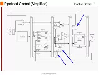
Pipelined Control (Simplified) Chapter 4 — The Processor — 18
Pipelined Control • Control signals derived from instruction • As in single-cycle implementation Chapter 4 — The Processor — 19
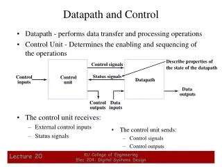
The Control Signals by Phase • Instruction Fetch There are no control signals specific to this stage. • Instruction Decode There are no instruction–specific control signals in this step. • Execute • There are three control signals associated with this step. • RegDst This selects which field, IR[20:16] or IR[15:11] will be used as theregister destination number for the Write Register in WB. The five bit value selected is written into EX/MEM and copied to MEM/WB. • ALUOp This is the two–bit selector of the ALU operation. • ALUSrc This discrete control signal selects the B input to the ALU.
Control Signals by Phase • Memory Access • There are three control signals associated with this step. • BranchThis indicates that a branch instruction is in this stage. • MemRead The ALU output is used as a memory address that is read.This is set by the LW instruction. • MemWrite The ALU output is used as a memory address, to whichthe contents of the specified register are written.This is set by the SW instruction. • Write Back • There are two control signals associated with this step. • MemToReg This selects either the ALU output or memory output tobe written back to the register file • RegWrite This causes the selected value to be written to the specified register.
Pipelined Control Chapter 4 — The Processor — 22
Data Hazards in ALU Instructions • Consider this sequence: sub $2, $1,$3and $12,$2,$5or $13,$6,$2add $14,$2,$2sw $15,100($2) • We can resolve hazards with forwarding • How do we detect when to forward? §4.7 Data Hazards: Forwarding vs. Stalling Chapter 4 — The Processor — 24
Dependencies & Forwarding Chapter 4 — The Processor — 25
Detecting the Need to Forward • Pass register numbers along pipeline • e.g., ID/EX.RegisterRs = register number for Rs sitting in ID/EX pipeline register • ALU operand register numbers in EX stage are given by • ID/EX.RegisterRs, ID/EX.RegisterRt • Data hazards when 1a. EX/MEM.RegisterRd = ID/EX.RegisterRs 1b. EX/MEM.RegisterRd = ID/EX.RegisterRt 2a. MEM/WB.RegisterRd = ID/EX.RegisterRs 2b. MEM/WB.RegisterRd = ID/EX.RegisterRt Fwd fromEX/MEMpipeline reg Fwd fromMEM/WBpipeline reg Chapter 4 — The Processor — 26
Detecting the Need to Forward • But only if forwarding instruction will write to a register! • EX/MEM.RegWrite, MEM/WB.RegWrite • And only if Rd for that instruction is not $zero • EX/MEM.RegisterRd ≠ 0,MEM/WB.RegisterRd ≠ 0 Chapter 4 — The Processor — 27
Forwarding Paths Chapter 4 — The Processor — 28
Forwarding Conditions • EX hazard • if (EX/MEM.RegWrite and (EX/MEM.RegisterRd ≠ 0) and (EX/MEM.RegisterRd = ID/EX.RegisterRs))ForwardA = 10 #Two bit control signal to MUX • if (EX/MEM.RegWrite and (EX/MEM.RegisterRd ≠ 0) and (EX/MEM.RegisterRd = ID/EX.RegisterRt))ForwardB = 10 • MEM hazard • if (MEM/WB.RegWrite and (MEM/WB.RegisterRd ≠ 0) and (MEM/WB.RegisterRd = ID/EX.RegisterRs))ForwardA = 01 • if (MEM/WB.RegWrite and (MEM/WB.RegisterRd ≠ 0) and (MEM/WB.RegisterRd = ID/EX.RegisterRt))ForwardB = 01 Chapter 4 — The Processor — 29
Double Data Hazard • Consider the sequence: add $1,$1,$2add $1,$1,$3add $1,$1,$4 • Both hazards occur • Want to use the most recent • Revise MEM hazard condition • Only fwd if EX hazard condition isn’t true Chapter 4 — The Processor — 30
Revised Forwarding Condition • MEM hazard • if (MEM/WB.RegWrite and (MEM/WB.RegisterRd ≠ 0)and not (EX/MEM.RegWrite and (EX/MEM.RegisterRd ≠ 0) and (EX/MEM.RegisterRd = ID/EX.RegisterRs)) and (MEM/WB.RegisterRd = ID/EX.RegisterRs)) ForwardA = 01 • if (MEM/WB.RegWrite and (MEM/WB.RegisterRd ≠ 0)and not (EX/MEM.RegWrite and (EX/MEM.RegisterRd ≠ 0) and (EX/MEM.RegisterRd = ID/EX.RegisterRt)) and (MEM/WB.RegisterRd = ID/EX.RegisterRt)) ForwardB = 01 Chapter 4 — The Processor — 31
Datapath with Forwarding Chapter 4 — The Processor — 32
Load-Use Data Hazard Need to stall for one cycle Chapter 4 — The Processor — 33
Load-Use Hazard Detection • Check when using instruction is decoded in ID stage • ALU operand register numbers in ID stage are given by • IF/ID.RegisterRs, IF/ID.RegisterRt • Load-use hazard when • ID/EX.MemRead and ((ID/EX.RegisterRt = IF/ID.RegisterRs) or (ID/EX.RegisterRt = IF/ID.RegisterRt)) • If detected, stall and insert bubble Chapter 4 — The Processor — 34
How to Stall the Pipeline • Force control values in ID/EX registerto 0 • EX, MEM and WB do nop (no-operation) • Prevent update of PC and IF/ID register • Using instruction is decoded again • Following instruction is fetched again • 1-cycle stall allows MEM to read data for lw • Can subsequently forward to EX stage Chapter 4 — The Processor — 35
Stall/Bubble in the Pipeline Stall inserted here Chapter 4 — The Processor — 36
Stalls and Performance • Stalls reduce performance • But are required to get correct results • Compiler can arrange code to avoid hazards and stalls • Requires knowledge of the pipeline structure The BIG Picture Chapter 4 — The Processor — 37