Download
1 / 38
730 likes | 1.83k Views
Chapter 5 Auto-Pilot. Avionics and Aircraft Electrical Systems. Auto-Pilot. Learning Objectives. By the end of the lesson you should have an understanding of the need for an auto-pilot and how it controls the aircaft. Auto-Pilot. Why do we need an auto-pilot?.

E N D
Chapter 5 Auto-Pilot • Avionics and Aircraft Electrical Systems
Auto-Pilot Learning Objectives By the end of the lesson you should have an understanding of the need for an auto-pilot and how it controls the aircaft.
Auto-Pilot Why do we need an auto-pilot? Long periods of flying are very tiring. Allows pilot to concentrate on other duties. Gives a smoother ride to passengers. Allows complicated routes to be flown easily. Can stop the aircraft being put in dangerous situations. Makes life easier for the pilot.
Auto-Pilot Types Of Auto-Pilot Basic Gyro Stabilised. This type is a mechanical system which takes inputs from the pilot or navigational systems to fly the aircraft. With this type the pilot would manually fly the aircraft for take-off and landing and any other unusual manoeuvre. After engaging the auto-pilot the aircraft would be controlled by the pilot making selections on the auto-pilot control box. The pilot still has to monitor the system to maintain the aircraft within it’s operating parameters. Therefore this type of auto-pilot takes some of the load off of the pilot but can still be tiring.
Auto-Pilot Computer Controlled. This system usually has three identical computers that are programmed to fly the aircraft within it’s capabilities. They take inputs from various aircraft systems to monitor what the aircraft is doing and also commands programmed into the computers by the pilot. With this system the auto-pilot can in some cases fly the aircraft from take-off to landing and the pilot would not manually fly the aircraft except in an emergency. The computer can even be programmed to carry out a missed approach so that the pilot only has to press a TOGA (Take Off and Go Around) button and the computer will select the actions required. Even in an emergency it is sometimes better for the pilot to put commands into the auto-pilot rather than take control.
Auto-Pilot On carrier based aircraft the auto-pilot is used for take-off for safety reasons. This leaves the pilot free to hold the ejection seat handle to shorten reaction time if ejection is required.
Auto-Pilot Typical Auto-Pilot Controller
Auto-Pilot Principle Of Operation (Basic Auto-Pilot) To control an aircraft requires two operations: A way of detecting when the aircraft has deviated from the required flight path. A system for calculating what control movements are needed to correct this error, and of making those control movements. If the aircraft is disturbed nose up then a control movement is required to bring the nose back down to restore level flight. This control movement needs to be proportional to the size of the disturbance. So a small disturbance requires a small correction and a large disturbance requires a large correction.
Auto-Pilot Because the aircraft needs to be controlled in the three axis of pitch, roll and yaw, three channels are needed in the auto-pilot to control each axis Rate Gyroscope This is the device which detects the disturbance. It is usually a spinning mass which is electrically driven. The gyroscope resists any disturbance by generating a force to oppose it, and this can be detected electrically by a sensor. An electrical signal is generated in proportion to the size and speed of the disturbance, amplified and fed to the second part of the system, the correction circuit.
Auto-Pilot These rate gyros are mounted on each axis and measure any change in direction and the rate of change. Servo Motors The disturbance correctors are servo-motors which are designed to operate at a speed proportional to the size of the signal applied to them. These servo-motors are connected to the powered flying controls and operate the control valve on the powered flying control. As the aircraft returns to it’s original flight path the signal will reduce and so the correcting action.
PFCU - Motor On Main Pump Servo Pump Light Out Constant Pressure Assembly Oil Sump (OM 15) Mechanical Spring Lock Released
PFCU - Autopilot Engaged 1. Torquemotor unlocked
PFCU - Autopilot Engaged • 1. Torquemotor • unlocked 2. Torque Limiter locked
PFCU - Autopilot Engaged • 1. Torquemotor • unlocked • 2. Torque Limiter • locked 3. Spring Strut locked
PFCU - Autopilot Engaged • 1. Torquemotor • unlocked • 2. Torque Limiter • locked 4. Feedback Transmitter • 3. Spring Strut • locked
PFCU - Autopilot Engaged 1. Torquemotor unlocked 2. Torque Limiter locked 4. Feedback Transmitter 3. Spring Strut locked
PFCU - Autopilot Engaged Autopilot signals Torquemotor
PFCU - Autopilot Engaged Autopilot signals Torquemotor
PFCU - Autopilot Engaged • Autopilot signals • Torquemotor • x • Differential • Linkage • Assembly • Locked Main Servo Valve moves
PFCU - Autopilot Engaged • Autopilot signals • Torquemotor • Main • Servo • Valve
PFCU - Autopilot Engaged • Autopilot signals • Torquemotor • Main • Servo • Valve
PFCU - Autopilot Engaged • Autopilot signals • Torquemotor • Main • Servo • Valve
PFCU - Autopilot Engaged • Autopilot signals • Torquemotor Differential Linkage Assembly Locked • Main • Servo • Valve
PFCU - Autopilot Engaged • Autopilot signals • Torquemotor • Differential • Linkage • Assembly • Locked • Main • Servo • Valve Transfer to Slave PFCUs
PFCU - Autopilot Engaged Autopilot Torquemotor • Differential • Linkage • Assembly • Locked • Main • Servo • Valve Feedback Transmitter Info to Torquemotor • Transfer to • Slave PFCUs
PFCU - Autopilot Engaged • Autopilot • Torquemotor • Differential • Linkage • Assembly • Locked Main Servo Valve Feedback Transmitter Info to Torquemotor • Transfer to • Slave PFCUs
PFCU - Autopilot Engaged • Autopilot • Torquemotor • Differential • Linkage • Assembly • Locked Feedback Transmitter Info to Torquemotor • Transfer to • Slave PFCUs
Auto-Pilot Yaw Dampers On large aircraft an oscillation known as Dutch Roll occurs mainly at altitudes above FL240. This is when the tail of the aircraft starts to move in a circular motion and grows rapidly. This movement causes the wings to start rocking and if not stopped it can develop into a very violent and dangerous amplitude where the aircraft would be overstressed. The method used to stop this is to use a rate gyro to pick up the Dutch Roll and feed corrections to the rudder channel of the auto-pilot. These rate gyros are called Yaw Dampers and operate continually even with the auto-pilot disengaged.
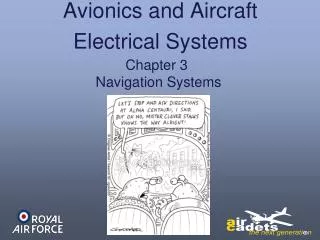
Auto-Pilot TM Yaw Damper Circuit RUDDER YAW RATE GYRO PFCU RUDDER PEDALS Other Systems Other aircraft systems can be coupled to the auto-pilot to control the flight path. i.e. INS/GPS, ILS,VOR, Altimeters and Terrain Following Radar Systems.
Auto-Pilot Modes Of Operation Altitude Lock When selected the auto pilot will maintain the selected altitude. Speed Lock When selected the auto pilot will maintain the selected IAS or Mach No by controlling the engine throttles. Heading Lock When selected the auto pilot will maintain the selected heading. Navigation Lock When selected the auto pilot is coupled to a navigation beacon i.e. VOR, TACAN or ILS and will navigate to the beacon.
Auto-Pilot INS/GPS Lock When selected the auto pilot will follow the complete route programmed into the navigation device. Auto Land Used to put the aircraft on the threshold when the visibility is below normal pilot limits. Only airfields certified to operate at the require standard are authorised for auto land systems. The aircraft is coupled to the ILS and speed lock and automatically follows the ILS signals to the threshold. As the aircraft approaches the ground the radar altimeter is used to detect the height above the ground and the aircraft automatically rounds out at the correct height and closes the throttles to place the aircraft on the runway.
Auto-Pilot Terrain Following Radar Some military aircraft that fly at low level (100-250ft AGL) have an aid for the pilot which plots the surface of the ground. This system can be coupled to the auto pilot and a height AGL to be flown selected and the auto pilot will fly the aircraft to maintain the height above the ground. Total Auto Flight With modern computer controlled aircraft a complete flight can be programmed into the system which will take the aircraft off, climb to the selected altitude, follow the route to the destination, descend the aircraft and carry out an auto land.
Auto-Pilot Conclusion You should now understand the need for an auto-pilot and how it controls the aircraft.