Download

1 / 57
570 likes | 711 Views
SILICON DETECTOR MEETING BNL, SEPTEMBER 26, 2006 MECHANICAL STRUCTURE STUDY. CONTENCE. 1. ASSUMED LAYOUT 2. SUPPORT FLANGES DESIGN 3. SRESSES AND DIFLECTION STUDY 4. STAVE ANALYSIS 5. OPEN QUESTIONS. B-layer (with beam-pipe) 2 Pixel Layers (Green) + Discs 4 SS Layers (Blue) + Discs

E N D
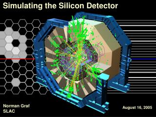
SILICON DETECTOR MEETINGBNL, SEPTEMBER 26, 2006MECHANICAL STRUCTURE STUDY
CONTENCE • 1. ASSUMED LAYOUT • 2. SUPPORT FLANGES DESIGN • 3. SRESSES AND DIFLECTION STUDY • 4. STAVE ANALYSIS • 5. OPEN QUESTIONS
B-layer (with beam-pipe) 2 Pixel Layers (Green) + Discs 4 SS Layers (Blue) + Discs 2 LS (Red) + EC Discs (Red) 1-1
Staves incline to take in to account the Lorenz angle, (170) 1-3
SUPPORT STRUCTURE FOR:- OUTER LAYER (5 flanges, RED);- MIDDLE LAYER (3 flanges, BLUE);- INNER LAYER (3 flanges, GREEN). 2-4
SUPPORT FLANGES 2-1
Rail Locations 2-7
Preliminary Calculations: Vertical and Horizontal deformations and stresses 3-1
Stress is low – Safety factor over 30 Carbon. 200kg 200kg 3-2
Max deflection calculated: 50m Deflection 50mkm max 3-3
Deflection in Z: 5 mm if pulled individually. 2 forces 20 kg each 3-4
Def= .389 mm (-y) 2 Meters with no Central support. Deflection too large. Central support. Def= .389 mm (-y) 4-4
Stress, middle section S=1.142 MPa 4-6
OPEN QUESTIONS. 5-1
Layout Issues • Assume: 3+4+2 Layers • Discs – (not studied yet) • Flat or Cone? • Inner discs installed together with the Barrel • Service Routing • Present layout implies large number of bends need to see if this is possible. 5-2
Mechanical Structure Specifications • Need to agree on specification for: - Stave max deflection - Assembly stability (Thermal, Mechanical…) • Assembly on the surface (Pixel layers, SS and LS) • Full assembly installed in Hall. (See assembly seq. developed by Sue Duffin) • Adjustments in Situ? Do we need to be able to adjust in Situ? • Number of support points for the structure off the Rails. 5-3
Stave Interface • Stave Interface in Z: • Fixed at Z=0? Free at large Z. • Fixed and large Z free at Z=0? • Stave Fixation in R-f • How much access do we need during assembly? • Staves overlapping at Z=0 ? ( gap ore no gap). 5-4
Services Interface • Assume all Services are mounted on the Support structure and are strain relief. Min stress to apply to the Stave. • If Stave is fixed at Z=0 need to make sure there are no thermal stresses that develop during cool down. 5-5
Modularity – Installation Sequence • Surface Assembly of the Barrel • Assemble as much of the Barrel as possible. • In this version we assume that we can assemble part of the disks already on the surface – this needs detail Eng. Studies. • The installation sequence of ID in the pit. • Step I: Moderator and services on IWV • Step II: Barrel Surface assembly • Step III: Barrel Services (cables, pipes) • Step IV: Outer Discs • Step V: Outer Discs services • Step VI: b-layer + beam pipe