Chapter 6-2. Carrier injection under forward bias
100 likes | 527 Views
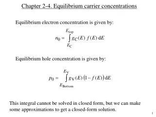
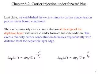
Chapter 6-2. Carrier injection under forward bias. Last class, we established the excess minority carrier concentration profile under biased conditions.

Chapter 6-2. Carrier injection under forward bias
E N D
Presentation Transcript
Chapter 6-2. Carrier injection under forward bias Last class, we established the excess minority carrier concentration profile under biased conditions. The excess minority carrier concentration at the edge of the depletion layer will increase under forward biased condition. The excess minority carrier concentration decreases exponentially with distance from the depletion layer edge.
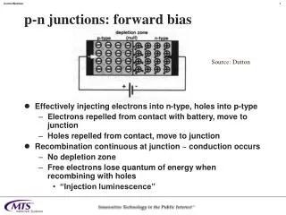
Carrier injection under forward bias At equilibrium, # of holes diffusingto n-side equals # of holes driftingfrom n-side. When we apply external forward voltage, VA, holes diffusing (injection) to n-side from p-side increases exponentially. This increases the hole concentration at the edge of the depletion layer on n-side. Similarly,
Minority carrier concentration profile under bias + VA np(0) pn(0) np= np0 + np(x'') pn = pn0 + pn(x') pn0 np0 x'' x'
Carrier injection under forward bias (continued) Change of axes to x' and x'' (see graph) x' axis x'' axis
General current and minority carrier diffusion equations Simplified equations
x' x'' Current equations applied to a diode Find Jn and Jp at the edge of the depletion layer and add them to get the total current. Assumption: No generation or recombination inside the depletion layer
Current equations applied to a diode Therefore,
Diode current equations Similarly, Current due to electrons will be along positive x' direction. And total current equals, Shockley equation
Forward and reverse bias characteristics Large forward bias (VA >> kT/q): Large reverse bias (VA << – kT/q): J
Example 1 Figure 6.3 is a dimensioned plot of the steady state carrier concentration inside a pn junction diode maintained at room temperature. • Is the diode forward or reverse biased? Explain • Do low-level injection conditions prevail in the quasi-neutral region of the diode? Explain • Determine the applied voltage, VA • Determine the hole diffusion length, Lp