Download
1 / 28
290 likes | 449 Views
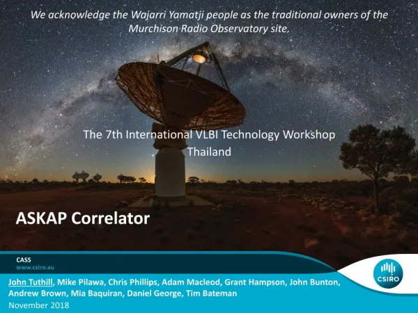
We acknowledge the Wajarri Yamatji people as the traditional owners of the Murchison Radio Observatory site. ASKAP Correlator. The 7th International VLBI Technology Workshop Thailand. CASS.

E N D
We acknowledge the WajarriYamatji people as the traditional owners of the Murchison Radio Observatory site. ASKAP Correlator The 7th International VLBI Technology Workshop Thailand CASS John Tuthill, Mike Pilawa, Chris Phillips, Adam Macleod, Grant Hampson, John Bunton,Andrew Brown, Mia Baquiran, Daniel George, Tim Bateman November 2018
ASKAP Instrument Overview FPGA-based Hardware Correlator design performance Oversampled filterbanks, why? ASKAP Extensions Other research and projects Outline: ASKAP Correlator | John Tuthill
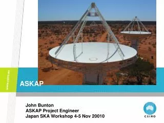
ASKAP- Australian SKA Pathfinder Area: 41,200 km2 Population: 120 (3 milli-persons per km2) ASKAP Digital Beamformer | John Tuthill
188 elements (94 elements in each polarisation) Analogue RF bandwidth: 700MHz to 1.8GHz Band 1: 700MHz – 1,200MHz Band 2: 840MHz – 1,440MHz Band 3: 1,400MHz – 1,800MHz Field of View 30 deg2 Analogue RF over Fibre (RFoF) Thermoelectric coolers 36 x 12m dia. dishes Max baseline = 6 km ~3000m2 effective collecting area ASKAP PAF ASKAP Correlator | John Tuthill
ASKAP: Architecture and signal chain • Custom digital system: • Raw data ingest: 130Tbits/s • Raw processing power: 2.3PMAC’s/s Mk-II PAF: checkerboard array, LNAs, RF filters, laser drivers Central Site DSP: FPGA Hardware Correlator Ethernet Raw Visibilities Optical-to-electrical, Samplers, Coarse filterbanks Beamformers, Fine filterbanks RF over Fibre Imaging pipeline : iVEC“Galaxy” Cray Inc. XC30 series supercomputer Located in Perth, ~800km from MRO. ~200 TeraFLOPS ASKAP Correlator | John Tuthill
ASKAP DSP Hardware Passive optical circuits for data cross-connects Redback-3 platform Correlator Dragonfly-3 Digital Receiver Beamformer ASKAP Correlator | John Tuthill
ASKAP – Digital Receiver Dragonfly-3 Digital Receiver • Sampling • Resolution 12bits (9.4 ENOB) • Analog BW 2.8GHz • Direct digital down-conversion (2nd and 3rd Nyquist zones) • Sample rates: 1,280MSps and 1,536MSps • Coarse frequency channelization • Processed bandwidth: 384 MHz(arbitrarily selectable anywhere in the observing band) • Coarse frequency channels: 1MHz oversampled by 32/27 • Spectral flatness: <0.2dB • Sub-band alias rejection: >60dB ASKAP Correlator | John Tuthill
ASKAP – Beamformer Redback-3 DSP Platform • Digital beamforming • Narrow-band beamformer structure (weight-and-sum) • Full 192x192 array covariance matrix for each 1MHz channel • Up to 72 single-polarized beams (usually configured as 36 dual-pol beams) • Fine frequency channelization • 6 frequency “zoom” modes:18.5kHz, 9.3kHz, 4.6kHz, 2.3kHz, 1.2kHz, 580Hz • Critically sampled • Delay tracking and fringe-stopping • Coarse delay to 1us resolution • Time-varying phase slope applied to fine channels ASKAP Correlator | John Tuthill
ack. Aidan Hotan ASKAP Max SNR Beamforming Noise Signal Signal + Noise - = Array Covariance Matrix Inverse Dominant Eigenvector x = ASKAP Correlator | John Tuthill
ASKAP – Correlator • Full Stokes correlator for • 630 Baselines • 36 dual-polarised beams • 15,552 spectral channels • Same hardware as beamformer • (Different FPGA firmware) • 5 second integrations • 32-bit float output • ~50Gbps over Ethernet • Visibilities streamed to Pawsey Centre HPC in Perth ASKAP Correlator | John Tuthill
Oversampled filterbanks:critically sampled case, order = 1024 Channel spacing = Output sampling rate Significant aliasing!!! “Scalloping” across the full-band Channel spacing = 1MHz Output sample rate = 1MHz Single output channel with two of the images Three output channels ASKAP Correlator | John Tuthill
Oversampled filterbanks:Fractionally over-sampled case (8/7), order = 1024 Channel spacing < Output sampling rate Aliasing reduced from -6dB to -50dB!! Almost no “Scalloping” Channel spacing = 1MHz Output sample rate = 1.1429MHz Single output channel with two of the images Three output channels ASKAP Correlator | John Tuthill
Oversampled filterbanks:Full-band response Critically sampled Over sampled ASKAP Correlator | John Tuthill
Oversampled filterbanks:Notes • Allows independent control of channel response and aliasing characteristics • Increases the overall output data rate by the OS factor • Sample rates no longer conform to VDIF specification • Using a prototype “CODIF” format for Effelsberg and Jodrell Bank • CODIF - CSIRO Oversampled Data Interchange Format (provisional) ASKAP Correlator | John Tuthill
Future work: ASKAP Tied-Array Commensal operation Uses existing FPGA-based hardware correlator Can start small and scale up Development compatiblewith FRB fast-dump correlator ASKAP Correlator | John Tuthill
New tech.: Xilinx RFSoC(RF System-on-Chip) • One chip!! • 12-bit RF-ADCs (+ DACs) • 16 x 2GSps or 8 x 4GSps • 4GHz analogue BW • Synchronous sampling across multiple devices • Processing system • Quad-core ARM Cortex-A53 • Dual-core ARM Cortex-R5 • Rich set of standard interfaces (DDR4, USB, ...) • FPGA fabric • ~1 million logic cells • ~4k hardware multipliers • Fast RAM • 32.75Gbps transceivers ASKAP Digital Beamformer | John Tuthill
RFSoC Projects: “Bluering”– currently in prototype HW development phase • Modular, scalable to 512 RF inputs (32 RFSoC devices) • RFoF inputs • Direct RF sampling • 12-bits • SNR: 66 dB • Cross talk: -70 dBc • Array-based DSP • Beamforming • Correlation • Channelisation • Synchronous transient capture • Physical/Electrical • Overall size: 600x600mm (TBD) • Weight: 20kg • Supply: 48V nominal @ 900W • Liquid cooled • Optical data transport • Off-system: 40GbE, SMF (40km) • Monitoring and Control: 10GbE SMF (40km) ASKAP Correlator | John Tuthill
RFSoC Projects: CABB upgrade & Cryo-PAF Prototyping CABB upgrade using theXilinx ZCU111 RFSoC board (very encouraging results so far!!) Future: Multi-channel sampler andback-end processor for theCryo-PAF project ASKAP Digital Beamformer | John Tuthill
Other Projects • Ultra-wideband feed system for Parkes 64m • CSIROSat-1: 3U CubeSat • Hyperspectral IR Earth imaging • On-board FPGA and SoC image processing • In-orbit re-programming • S-Band down-link • Technology demonstrator • Capability building ASKAP Correlator | John Tuthill
Star-on Machine Thank you Dr. Seuss - The Sneetches and Other Stories CSIRO Astronomy and Space Science Dr John TuthillResearch Group Leader | Signal Processing Technologies t +61 2 9372 4392 e john.tuthill@csiro.au w www.csiro.au/ CSIRO Astronomy and space science
“CODIF” prototype “CODIF” header ASKAP Correlator | John Tuthill
Future work: ASKAP Tied-Array Tied-Array Processor (TAP) cell ASKAP Correlator | John Tuthill
Detailed Signal Path – single PAF Digital Receiver Beamformer Number representation is fixed-point signed two’s complement throughout ASKAP Correlator | John Tuthill
Digital Beamformer (single DSP FPGA) ASKAP Correlator | John Tuthill
Individual 1MHz digital beamformer module ASKAP Correlator | John Tuthill
Beamformer engine performance All contributing PAF port voltagesmust be processed in 263 clocks • 18 single-pol beams: all 192 ports active • 36single-pol beams (1 replay): 130 active ports • 72single-pol beams (2 replays): 60 active ports Implications for sidelobe control, null-steering, spill-over control • Two main performance bounds: • Degrees of freedom in beam weight selection (architecture) • Maximum beam weight update rate (interface) • 1. Degrees of freedom (# active weights) • Sample rate = 1MHz x 32/27 -> T = 843.75ns • Beamformer logic clock = 312.5MHz • 18 physical instances of the beamformer process ~1 port voltage per clock cycle ASKAP Correlator | John Tuthill
Beamformer engine performance Implications for real-time/adaptive beamforming and RFI tracking • 2. Maximum weight update rate, determined by: • ACM dump time • Beam weight upload time • ACM data volume and dump time: 192 x 192 ports ÷ 2 (conjugate symmetry) x 2re/im x 32-bit float ≈172kBytes Measured ACM dump time ≈4ms/ACM (172kB/4ms = 43MB/s = 344Mb/s) (More efficient to stream raw port voltages than ACMs for dump times < 0.2ms) • Beam weight upload time ≈ 180ms/chassis (36 dual-pol beams, measured) Max “dynamic” beamforming period≈ 48 x 4ms + 180ms ≈ 400ms (does not include off-line weight calculation) ASKAP Correlator | John Tuthill
Beamforming Algorithm (where ) weights modified for smooth phase: Array covariancematrix W1 New beamformerweights + W2 x 384 1MHz frequency channels + S W188 + • Maximum SNR with phase matching • other approaches… • sub-space projection (RFI mitigation, see next presentation!) • Shape-constrained beamforming ASKAP Correlator | John Tuthill