Download
1 / 31
320 likes | 481 Views
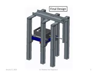
PMT Support Structure. Final Design. Enrique Calvo Alamillo KOBE - 3 March 2008. INDEX:. Status of gamma-catcher and target vessel tools fabrication. Final PMT distribution in the detector. Final design of PMT supports.

E N D
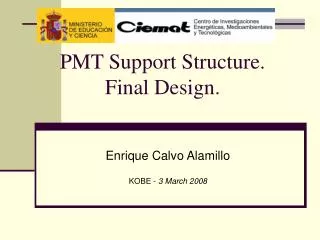
PMT Support Structure.Final Design. Enrique Calvo Alamillo KOBE - 3 March 2008
INDEX: • Status of gamma-catcher and target vessel tools fabrication. • Final PMT distribution in the detector. • Final design of PMT supports. • Mechanical devices to machine/weld the different fixation points on the buffer. • Pressure and buoyancy tests. • Status of acrylics and stainless steel production. • Final treatment and cleaning of materials. • Schedule of supports production, treatment, cleaning and delivery. • Assembly procedure. • Installation plan. • Interfaces with LED-fibers and magnetic sensors. • Next Steps. Double-Chooz Collaboration meeting (Kobe)
Status of gamma-catcher and target vessel tools fabrication. • (being built at CIEMAT workshop) At Madrid are under fabrication 4 different tools kind following the drawing supplied by Saclay: • One tool unit for the gamma catcher. • Two rotation tools units. Both things ready and delivered to Saclay. Commissioning of the tools at Madrid. Tilt test at Saclay. Double-Chooz Collaboration meeting (Kobe)
Three tools units for the target. Will be ready mid of March. And delivered to Saclay Mid of April. ‘BENITO’ welding the base of the tool. • One tool unit for the transport. Will be ready on final March. And delivered to Saclay Mid of April. Double-Chooz Collaboration meeting (Kobe)
2. Final PMT distribution in the detector. This is the last approved distribution. That was simulated by Glenn. The positioning precision of the PMTs will be approximately +- 1 cm and +- 1º. The orientation of the PMTs on the lids it is toward the center. On the cylinder is not toward the center. Double-Chooz Collaboration meeting (Kobe)
3. Final design of PMT Supports Structure. • PMT Asemmbly. This is the last approved PMT assembly. Composed for 1.4 kg of Acrylic and 1.1 kg of magnetic shielding. Double-Chooz Collaboration meeting (Kobe)
Those are the PMT assembly on the cylindrically side of the Buffer. • Those are the PMT assembly PMT assembly on the Top and Bottom lids of the Buffer. Detail of the intern fixation elements of the PMT to the assembly. Double-Chooz Collaboration meeting (Kobe)
PMT Support Structure. • One of six sector of PMTs distribution on the buffer. • Shown the Detector axis directions, respect of the center. • X toward the exit of the caver. (Longitudinal axis of the caver) • Y transversal axis of the caver. • Z vertical axis. Double-Chooz Collaboration meeting (Kobe)
Top and lateral view of the sector. Double-Chooz Collaboration meeting (Kobe)
Top and Bottom fixation structure on the buffer lids. This structure is composed by 2 central ring and 3 sector of circles. Attached to some pieces welded to the buffer wall. Double-Chooz Collaboration meeting (Kobe) The PMTs are fixed to the structure by 2 M6 screws on each side.
Cylindrical fixation structure on the buffer. This structure is composed by 30 circumferential sector of two independent vertical L profiles, distributed on 3 vertical step. Frontal view of the sector Top view of the sector Double-Chooz Collaboration meeting (Kobe)
L vertical profile. Those are attached to the buffer circumferential reinforces by M6 holes on both extremes of the profile. The PMTs are fixed to the structure by 2 M6 screws on each side. Double-Chooz Collaboration meeting (Kobe)
4. Mechanical devices to machine/weld the different fixation points on the buffer. • Tool to drill the holes on the cylindrical buffer wall. • This will allow to drill the holes on the buffer wall to fix the vertical L profiles within the needed tolerance. • The design will be ready very soon. • Tool to weld the pieces on the Lids. • Will allow to position the pieces to be welded, to mount the rings and circular sectors on. The design will be ready very soon. Those tools will be delivered to saclay Mid of April. Double-Chooz Collaboration meeting (Kobe)
5. Pressure and buoyancy tests. • Final tests have been done with Iuri Pepe collaboration (Centro Brasileiro de Pesquisas Fisicas – BRAZIL). • The document was inserted on EDMS: https://edms.in2p3.fr/document/I-012678/1 • Buoyancy test: The buoyancy test has been carried out using the pressure box. The PMT assembly system was attached to a fixing support needed to place the PMT at 90º with respect to the vertical wall inside the pressure box. This corresponds to the most critical orientation because the expected torque due to the buoyancy force is maximal. Double-Chooz Collaboration meeting (Kobe)
This box was filled with white mineral oil (Aldrich M3516-spec). The fill-up/empty-down operation was done by moving up and down a 200 liter drum hanged by a crane. A plastic pipe assures the oil transfer between the two vessels. Double-Chooz Collaboration meeting (Kobe)
The angular change in the PMT position was reading using a millimeter square ruler glued to the back plane of the pressure box, serving as reference frame. Four mechanical check points were used for under pressure displacement measurements. Two of them were fixed to the PMT fixing system used in the pressure box (1 and 2) and the other two were attached to the PMT acrylic assembling (3 and 4). The idea was to distinguish the effect of the possible displacement due to the fixing support from the deformation of the PMT acrylic support. A digital camera mounted on a tripod has been used as data recorder. Afterwards the photographs have been analyzed in such a way to determine movements. The PMT and the mu-metal assembling experiment a rotation of (0.97º +/- 0.52º). This rotation is just apparent since the PMT test box fixing system contribute with (0.60 +/- 0.15º) of this turning. The angular difference between the two rotation angles is the deformation of the acrylic base support and it is Dq = (0.4 +/- 0.5º). Double-Chooz Collaboration meeting (Kobe)
A second test was devoted to determine if a differential up-ward movement can occur between the mu-metal and the PMT inside it. The mu-metal cylinder has been substituted by a half, twice thick, Inox cylinder. This set up allows to have a clear view of the PMT and the mu-metal cylinder inside the pressure box. Two check points bars have been installed, one on the mu-metal and a second one on the PMT it-self. No differential displacement could be measured within our system precision. Double-Chooz Collaboration meeting (Kobe)
Pressure test: In Double Chooz the PMTs located in the bottom part of the buffer will remain under a pressure < 0.5 bar once the vessel will be filled with oil. We have to check if our PMT system could be affected by such a level of pressure (The Hamamatsu R7081PMTs are able to operate up to 7 bar). Using the same setup, a pressure test was performed. The oil was transferred to the pressure test box using the system discussed before. A plastic pipe was fixed on the top of the box and it was filled with oil up to the maximal height allowed by the testing hall (9 m). Once the column is filled, the equivalent pressure applied to the PMT system was ~0.74 bar. To raise the oil level up to the desired height, a pressurized air line was applied to the oil drum. The whole system has been kept at ~0.74 bar for 20 minutes. After this time, the box was emptied and the PMT system has been thoroughly examined. No damagehas been observed in the PMT and/or in the mechanical structure tested. Double-Chooz Collaboration meeting (Kobe)
6. Status of acrylics and stainless steel production. • The acrylic pieces: The 7 different kinds of acrylic pieces production was started. We had several hundred of pieces produced. 840 to build. 1640 to build. 1640 to build. 840 to build. 420 to build. Double-Chooz Collaboration meeting (Kobe) 420 to build. 1680 to build.
The Inox pieces: • There are 15 different inox pieces to produce. The fabrication is not started yet. 12 to build. 24 to build. 36 to build. 48 to build. 60 to build. 60 to build. 60 to build. 60 to build. 30 to build. Double-Chooz Collaboration meeting (Kobe)
The support structure: There are 13 different inox pieces to produce. The fabrication is under progress. • On cylinder Buffer 65+65 to build. 32+32 to build. Double-Chooz Collaboration meeting (Kobe)
On lids Buffer 140 to build. 2 assemblies to build. 6 assemblies to build. Double-Chooz Collaboration meeting (Kobe)
7. Final treatment and cleaning of materials. To be decided in Kobe meetings. Those are our actual understanding. Acrylics 1. Wipe with mild soap and distilled water. 2. Rinse with distilled water. 3. Heat treatment (at 80º during 14 h).4. possible ultrasonic batch (distilled water + soap). 5. Rinse with distilled water. 6. Dry (pressurized air) 7. Pack in sealed plastic double bag. Stainless steel 1. Wipe with mild soap and DI water. 2. Passivation/descaling. 3. Ultrasonic bath (only for small pieces) with soap and DI water. 4. Rinse with DI water.5. Dry. 6. Pack in sealed plastic bag. Stainless Steel screws: 1. Ultrasonic bath with soap and DI water. 2. Rinse with DI water.3. Dry. 4. Pack in sealed plastic bag. Nylon screws and clips: 1. possible ultrasonic batch (distilled water + soap). 2. Rinse with distilled water. 3. Dry. 4. Pack in sealed plastic bag. Double-Chooz Collaboration meeting (Kobe)
8. Schedule of supports production, treatment, cleaning and delivery. • The acrylic pieces: All acrylic pieces that compound the PMT assembly will be ready to be delivered to Heidelberg during may. • The Inox pieces: All inox pieces to fix the PMT assembly to the support structure will be ready to be Delivered to Heidelberg during july. • The support structure: All inox support pieces will be ready to be delivered to Chooz during September. Except the pieces to weld on the buffer that will be delivered to Saclay mid of April. Double-Chooz Collaboration meeting (Kobe)
9. Assembly procedure. • Design of final tools and detailed procedure to mount the assembly of the PMTs will be ready before summer. Double-Chooz Collaboration meeting (Kobe)
10. Installation plan. • We have ready a first draft to start discussions. Was developed with Iuri Pepe collaboration (Centro Brasileiro de Pesquisas Fisicas – BRAZIL). • Needed coordination with Tennessee to match with PMT testing on site. And Saclay to define the scaffolding. The final proposal document schemeneed to be sent to Patrick Perrin 2 months before installation. Double-Chooz Collaboration meeting (Kobe)
11. Interfaces with LED-fibers and magnetic sensors. • LED-fibers Following the Jeff and Lisa (Sussex) requirements. This was the proposal to adapt the diffuser proposed from Sussex to the PMT assembly. The diffuser block, that have two optical fiber wire, can be attached to the PMT assembly on 4 different positions. Using one of four M6 holes made on the acrylic pieces. • Light-injection points: • Two rings of ten points around the buffer wall. • Six points each at the top and the bottom. • Those position are not defined yet. Double-Chooz Collaboration meeting (Kobe)
Magnetic Sensors • Those pictures show the proposal from Glenn: • 8 probes distributed on the cylindrical part. • 2+2 on the top and bottom lids. • Is not totally implemented on the 3D yet. Double-Chooz Collaboration meeting (Kobe)
12. Next Steps. • Detailed step by step Cleaning Procedure for the PMTs mechanical support pieces. • Update the TDR with the new PMT distribution and final PMT support • Define the assembly procedure for the PMTs support/assembly pieces. Update TDR. • Detailed installation process of the PMTs on the buffer. • Define the tooling necessary for those Jobs. • Define space, time and man-power requirements to do previous tasks . Double-Chooz Collaboration meeting (Kobe)