Download
1 / 32
320 likes | 346 Views
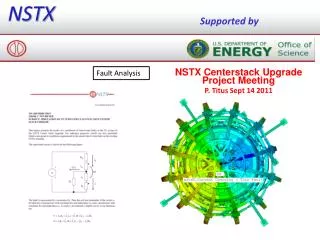
This comprehensive report covers the background, requirements, forces, thermal effects, contact resistance, and features of a new design for the TF joint, including recovery activities, design analysis, testing details, current waveforms, and thermal cycles. It also discusses the functions of the joint, load paths, thermal effects, contact resistance, and key design features.

E N D
Topics • Backround • Requirements • Forces and Load Paths • Thermal Effects • Contact Resistance • Features of New Design • Performance of New Design
BACKGROUND • TF joint failed on February 14, 2003 due to structural weaknesses • Project has developed a more robust design....... • factor in lessons learned from failure • all engineering aspects analyzed at appropriate level of detail • testing as necessary for engineering input and design verification • reduced dependence on precision manufacturing/assembly • easier maintenance
DESIGN 3D modeling complete, including… • integrated TF inner leg bundle • coolant tube routing and bulkhead • outer leg connections Fabrication drawings complete, including… • conductors • flags • flag boxes • shear shoes • hub assembly • torque collar* * Under revision
ANALYSIS Structural FEA complete, including… • both tiers of conductors • out-of-plane load path through spline • collar and wet lay-up representation • in-plane, out-of-plane, thermal loads • SOFT, EOFT, EOP cases • Various off-normal cases • Other analysis complete, including… • force calculations • temperatures, including joint temperature rise • fastener sizing calculations • miscellaneous calculations • Torque Collar analysis continuing
TESTING • Component testing (design input data) consists of: • Pull-out tests on threaded inserts • - one time and cyclic at 100oC • Pull-out tests on bolts threaded in copper • - one time and cyclic • Friction coefficient and electrical resistance tests • Shear tests on torque collar attachment • Status: Complete except more data to be generated for torque collar shear at high compression • Prototype testing (design verification) consists of: • Mechanical mock-up of single joint for cyclic fatigue testing • Electrical mock-up of single joint tested at full current and I2T • Status: In Preparation
CURRENT WAVEFORMS • Engineering design accounts for PS response, inc’l L/R decay in case of fault from Imax • ∫I2T = 6.0 x 10⁹ A2-s for 3kG-4.5s • ∫I2T = 6.15 x 10⁹ A2-s for 6kG-0.6s • Design basis ∫I2T = 6.5 x 10⁹ A2-s which causes adiabatic T of 80oC in Cu • 6kG pulse is most critical for joint since forces are maximum and time for heat diffusion is minimum Short Pulse Long Pulse
NUMBER OF PULSES & THERMAL CYCLES • Assume 50,000 pulse requirement at 6kG • 10 yr*20 week*5day*8hr*6pulse/hr = 48,000 • Highly conservative • NSTX 5yr plan calls for … • 40% @ 3kG (25% EM load) • 40% @ 4kG (44% EM load) • 15% @ 5kG (69% EM load) • 5% @ 6kG (100% EM load) • 100% • Assume 1,000 thermal ratcheting cycles (= number of days) • 10 yr*20 week*5day = 1000 • drives flag fastener fatigue cycle requirement • assuming 12 pulse/hr rate to set thermal ratcheting (conservative)
EM FORCES 148kft-lb 3klb • In-Plane • vertical load and moment • due to magnetic pressure • from self-field • Out-of-Plane • lateral due to ItfxBz(oh&pf) • torsional due to ItfxBr(oh&pf) 2.3klb 4.7klb 9.3klb 40.8kft-lb Notes: All coils assumed at full current, worst case polarity (conservative) Forces equal and opposite on two ends of bundle
FUNCTIONS OF JOINT • Mechanical Function • Preload for High Contact Pressure • Structural Support Against EM & Thermal Loads • Maintain High Contact Pressure • Low Electrical Resistance and Dissipation • Peak Temperature within Limit • Electrical Function
LOAD PATHS Friction Shear Shoe Torque Collar Hub/Spline/VV
THERMAL EFFECTS • Vertical length of inner leg bundle from bottom to top increases by up to 0.35” during a pulse • Vertical length of inner leg from torque collar to top of bundle increases due to inner leg temperature rise, whereas flag and hub remain relatively cool • Radius of inner leg bundle increases bundle increases by approximately 0.006” during a pulse • Flag heats modestly during pulse (T ≈ 5oC) but can ratchet to T ≤25oC at rated duty cycle (conservative), r ≈ 0.005” in length
CONTACT RESISTANCE Tolerable Resistivity ≈ 2.5µΩ-in2 (700psi) Req’d Flat Top Time =0.6 sec Note: assuming constant resistivity along joint
CONTACT PRESSURE & RESISTANCE Rmax Pavg
KEY DESIGN FEATURES Shear Shoe Hub Disks Flag Flag bolts (studs) Flag Box Box Bolts (stud) Torque Collar
TORQUE COLLAR • Prior Design (August 7) • not vertically symmetric • Torque reacted through moment arm • New Design • vertically symmetric • torque reacted tangentially
VOLTAGE PROBES FOR IN-SITU JOINT RESISTANCE MEASUREMENT • • IDI 100526 Coaxial Probe • - commercial spring-loaded probe used in semiconductor test industry • 2 probes per flag, 1 connected to instrumentation, 1 redundant spare • All 72 joints monitored (maintenance @ 200A, real time at full current)
DESIGN HIGHLIGHTS • Solid (not split) flags insulated with 4 layers Kapton, glass wrapped, potted in 304SS boxes • Boxes attached to hub disks using 1/2” studs • Flags attached via 3/8” Inconel studs preloaded to 5000lbf • Shear shoe on outer edge of flags is bolted to ends of inner leg conductor using Inconel bolts, one vertical and one angled for moment reaction • 3-segmenttorque collar w/two 1/2” bolts @ 10000lbf per joint, 0.180” wet lay-up with better type of epoxy (Hysol E-120HP) • Collar transmits torque only to hub structure at 3 anchor points • Redundant voltage probes are located on each side of the flag
FEATURES OF OVERALLFEA MODEL • Includes All Essential Structural Components Contributing To Flag Joint Performance • FLAGS - BOXES • COLLAR - HUBS • CENTER STACK - BOLTS • SPLINES - UMBRELLA • etc. • Models non-linear behavior (friction) • 24 fold symmetry (collar gaps, etc. not modeled)
LOAD CASES EXAMINED • Time Points • START OF FLAT TOP (SOFT) • END OF FLAT TOP (EOFT) • END OF PULSE (EOP) • Conditions • Normal • Off Normal • Low Preload (60%) • High Friction Coefficient • Low Friction Coefficient
FEA USED TO ASSESS STRESSES, DISPLACEMENTS, CONTACT PRESSURES
Temperatures Well Below Limit of 120oC Max Temperature of 94oC Occurs Just After EOFT • Tflat = 0.7sec (vs. 0.6 req’t) • Bolt Holes not exactly modeled (+10oC) • OH constant at max current (-TBDoC) • Insignificant change from constant resistivity simulation Contact Region
OFF-NORMAL CASE: 60% PRELOAD • Peak Temperature ≈ 3oC Higher • Temperature Distribution Different • Current Redistribution Beneficial Notes: Held SOFT pressure conditions after SOFT due to lack of EOFT data Color scales different Normal Off-Normal
TORQUE COLLAR FEA Detailed analysis of prior design revealed high stress concentrations in wet lay-up due to lack of vertical symmetry
NEW TORQUE COLLAR FEA • preliminary results indicate adequate safety margins • work still in progress
All defects contributing to original failure have been addressed
CONCLUSIONS • New Design Corrects All Defects Associated with Original Design • New Design Has Sufficient Margins at 6kG (pending torque collar resolution) • Follow-on Activities Will Increase Confidence • Mechanical Prototype Testing • Electrical Prototype Testing • Instrumentation During Commissioning and Operations • - resistance measurement (200A maintenance and real-time) system • - temperature, strain, displacement)