Chip measurements
Chip measurements. Giovanni Darbo / INFN - Genova E-mail: Giovanni.Darbo@ge.infn.it Talk highlights: Test setups; Parametric tests (IDD, VDD, timing); Power up reset; Functional tests: FIFOs, FE config, Event Builder,…; Yield… very preliminary; Test vectors & wafer probing;

Chip measurements
E N D
Presentation Transcript
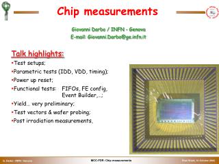
Chip measurements Giovanni Darbo / INFN - Genova E-mail: Giovanni.Darbo@ge.infn.it Talk highlights: Test setups; Parametric tests (IDD, VDD, timing); Power up reset; Functional tests: FIFOs, FE config, Event Builder,…; Yield… very preliminary; Test vectors & wafer probing; Post irradiation measurements.
Test Bench for Packaged MCC • HP-16700A: logic state/timing analyser & pattern generator mainframe. • HP-16716A: logic state/timing module for HP-16700A: • 167 MHz state, 333 / 667 MHz timing with 2 GHz timing zoom, 512 k samples state, 512k/1M samples timing, 68 / 34 channels. • HP-16722A: pattern generator module for HP-16700A: • 100 / 200 MHz, 256 K vectors, 40 / 20 channels. • HP-8110A: two channels 150 MHz pulse/pattern generator. • HP-E363xA: programmable power supplies. HP-8110A HP-E363xA MCC HP-16700A
IDD vs VDD Simulation explains measures
IDD vs CK frequency • Linear behaviour of IDD with respect to clock frequency; • The zero frequency IDD current is due to the LVDS I/O pads.
IDD vs VDD (CK = 40 MHz) • The 114 mA for IDD at 2.0 V could be reduced by 10-15 mA if the AMS compatibility pads will not be implemented; • For comparison: • MCC-AMS: IDD=55 mA @ VDD=3.3 V • MCC-D2: IDD=100 mA @ VDD=3.3 V
Timing: CK -> XCK • Delay between the input clock from the DORIC (CK) to the module system clock (XCK) is 5.1 ns CKp XCKp 5.1 ns
Timing: CK -> XCKIN -> DTO • In case of 40 Mb/s, CK rising is in the middle of the DTO/DTO2 transition. • In case of 80 Mb/s the CK and DTO/DTO2 transitions are almost in phase. • The relative timing of CK / DTO / DTO2 is irrelevant since it has to be adjusted at BOC/ROB level. DTOp CKp 9 ns Note: shown CK is early by 4 ns CK XCKIN DTO DTO2 10 ns
Timing: CK -> XCKIN -> LV1 • The rising edge of XCK is at 2/3 of the LV1 pulse. It should not be critical for FE operation. • All other MCC outputs (except DTO/DTO2 and STRO) have the same timing relationship with respect to XCK. LV1p CKp 11ns Note: shown CK is early by 4 ns 11 ns CK XCKIN DCI LV1 7 ns
Max operating frequency • Test of maximum operating frequency with no errors: • Two test vector patterns used: R/W register / FIFOs and Events • The two MCC clocks either tied together (CK=XCKIN, usual setup for MCC test) or XCKIN generated by CK trough XCK (CKXCK=XCKIN, module clock configuration). • Conclusion: MCC-I1 works in excess of 70 MHz @ 2.0 V.
RSIb: Considerations on the Test • Test vectors have Init part repeated only once and a Loop repeated indefinitely. • In the Init either a GlobalResetMCC or no command is inserted. In the Loop both a fast command (Sync) and a WrRegister and a RdRegister are executed. • When the MCC responds to both commands, the command decoder is “alive” and the MCC works in normal way (it my need a GlobalResetMCC to reset the other MCC blocks). Waveforms: (see next pages) • [1/4] Shows the command sequence; • [2/4] First run after power up. The MCC responds correctly to the Read/Write and to the Sync command after 131 kStates (the LSA samples the signals twice per clock cycles). This means that after 131132/8000 = 1.63 µs the MCC is alive (8000 is the number of LSA samples/µs). • [3/4] If the test is run a second time without a power cycle, the MCC always respond. • [4/4] If the same test is executed dropping the initial GlobalResetMCC the behaviour is the same. The GlobalRestetMCC is not able to reset the command decoder itself. Conclusion: • The MCC has been designed with the command decoder that always go to the “idle state” after a finite time. The longest time is about 64k states because it has a free running 16-bit counter that only when it pass from ‘0’ allows the command decoder to exit from some internal states and to reach the idle state. • The waveforms in the the next pages, documents the behaviour for MCC-0302. Not all the MCC tested need so long wakeup time, this depends on the configuration of the command decoder at power-up.
RSIb: The Test Vectors 1/4 GlobalResetMCC Loop init: Sync WrRegister FEEN 0xFFFF RdRegister FEEN Loop end. Sequence of serial commands to the MCC in SimPix script format. GlobalResetMCC Sync WrRegister FEEN 0xFFFF RdRegister FEEN Loop = 4.325 µs
RSIb: First Run after Power-up 2/4 DiffFlag = 1: MCC not responding DiffFlag = 0: MCC responding zoom
RSIb: Next Following Runs 3/4 DiffFlag = 0: MCC works zoom
RSIb: No GlobalResetMCC 4/4 Without an initial RSIb the MCC behaves in the way.
RSIb vs GlobalResetMCC • RSIb resets every single FF in the MCC in a single clock cycle, while the GlobalResetMCC is able to reset all the MCC blocks but the command decoder. The command decoder “auto resets itself” (go to idle state) in a definite time of < ~ 64k clock cycles. Only after the command decoder is in the idle state the MCC is able to respond to any command (GlobalResetMCC included). • With the test done, that confirm the design strategy for the command decoder used in the chip, we believe that the pin reset (RSIb) is not needed for system operation in the ATLAS detector. Another confirm to that, it is the operation of 7 MCC at the PS irradiation for several days and with many single event upsets: neither sign of dead lock has been seen or need of a pin reset have been necessary to restart the chip. • We still need the RSIb for testability of the chip. The RSIb puts the MCC in a well defined condition in a clock cycle after it is issued and it makes the test vectors more effective.
STRO Delay Measurements • Input vectors generated by SimPix; • Signals sampled by 2 Gsample/s Logic Analyser; • Use markers to get the time measure. DELAY
STRO Delay Conclusion • Delay circuit delays only STRO rising edge; • Delay linear to set value (6-bit): • Range = 0 (min) -> 0.4 ns/step • Range = 3 -> 0.8 ns/step • Range = 7 -> 1.4 ns/step • Range = 15 (max) -> 2.6 ns/step • STRO falling edge delay almost constant (~8 ns full range).
FE config In this example the command is RdFrontEnd(0x0,0x855) (10110.1011.0101.<0000.100001010101>8) . The CNT register have been loaded with 0x0009 that mean CNT<2:0>=1 (address/command) and CNT<15:3>=1 (data). The address/command part is scaled by 8 and so 8 CCK pulses are generated before LD goes high . While the data part is not scaled and so only 1 CCK is generated when LD is high . Only the 9-MSB data bits, out of the 12 bits (0x855), of the RdFrontEnd command are transferred to DAO . Because the command is a read command and the DTI2 is enabled the DTI2 signal is transferred to the DTO/DTO2 lines . The way the DTI2 signal is transferred to the DTO/DTO2 is by sampling the DTI2 with XCK starting from the 19th XCK after the init of the DCI command. MCC11_20.TIF 1 4 2 3 5
LV1 latency • The trigger command (Trigger = 1101), issued on the DCI line, generates a LV1 pulse to the FE chips. • The FE chips read the LV1 value sampling it with the rising edge of the system XCK clock. • The delay from the beginning of the DCI Trigger command to the rising of the LV1 signal is 200 ns, which corresponds to 8 clock units (see timing waveforms). TRIGGER LATENCY
SimPix / HP16700 Chip test Chip debug SimPix script HP16700 HP16700 SimPix COMPARE Test result Test result Test result
Functional Test: HP-16700 / SimPix • Functional test is made by state analyser driven by SimPix; • MCC command sequence generated by SimPixis converted to HP-16700 format and transferred to the pattern generator • MCC outputs are sampled by the state analyser and compared with SimPix high level model. • Precise signal timing is necessary to set HP-16700 probe sampling position to acquire stable signals in the state analyser. Each channel timing is individually adjusted. DCI Sampling Window Setup = 0 ns, hold 3 ns DCI Sampling Window Setup = 0 ns, hold 3 ns STATE ANALYSER Sampling CK TIMING ANALYSER 6 6
Event Building: View from HP-16700 MCC#4 - Receiver # 7 Disabled Mode 40 x 1 LV1 COMMAND TO MCC LV1 COMMAND TO FE’s MCC DTO/2 HITS FROM FE’s
Several Events seen by HP-16700 MCC#4 - Receiver # 7 Disabled Mode 40 x 1
Event building @ 40 MHz x 1 Event Event Dump
Event Building @ 40 MHz x 2 Same input events
MCC Yield • We do not have information on wafer yield for the MCC yet. The wafer test, differently from FE chips is committed to a firm (DELTA - Denmark). • We have measured many chips inside the package. From them we cannot extract a production yield value since we have had yield problems in dicing and wire bonding. • In addition, the first production batch (02/02) had a low production yield for FE-I with good chip only in the centre and at the wafer periphery (~15% FE-I yield). We have selected and packaged 15 MCCs coming from good FE reticles: 14 of them where working (see wafer map next slide). • 2+1 wafer (=112 x 3 MCCs) will be tested by DELTA next weeks...
Wafer Map with FEI/MCCI GOOD MCC BAD MCC Comment: good correlation between good FE-I and good MCC-I
Wafer and Production test • We decided to not test ourselves the chips on wafer, but to do it outside. We did the same for the MCC-AMS that were tested from AMS. Since IBM do not provide testing for they wafers we found DELTA as a possible solution. • DELTA will do parametric and functional tests (see test flow). The functional test will be executed at nominal 40 MHz clock speed (we do not think it is necessary to use higher speed). It is our responsibility produce the whole set of vectors. • Only 3 wafers from MCC-I1 will be tested for the moment, while all production wafers will be tested by them. • The 3 wafers are from the second IBM batch (6/02) which had high yield (70%÷80%) for FE-I.
Test flow for wafer testing 1) Open/short test: Force 0V at supply pins. Force e.g. -200uA at specified pins, sequentially, and measure voltage drop at negative protection diodes. Force e.g. +200uA at specified pins, sequentially, and measure voltage drop at positive protection diodes. 2) Power consumption: Bias specified pins according to some specified setup, loop a certain test pattern at specified frequency and measure average current consumption at supply pin. 3) Leakage test: Force low level at all inputs, but high level at the pin-under-test, measure input leakage high at specified pins. Force high level at all inputs, but low level at the pin-under-test, measure input leakage low at specified pins. 4) Input level test: Test a certain pattern with specified tight input levels. 5) Output level test: Set up a load current of specified value, run a certain pattern until specified vector number, measure level on outputs. 6) Functional test: Test certain functional patterns at specified frequency. 7) Other tests: Delay line characterisation
Functional test vector preparation Input pattern SimPix script HP16700 Verilog SimPix • 1.2 M vectors with functional test prepared • Other 400 k vectors generated by ATPG using scan chain. Scan chain alone gives > 90 fault coverage. COMPARE I/O pattern Test vector
ATPG Coverage Report Scan chain and ATPG vectors do not apply stimuli to the FIFO boundary: this limits the total coverage to 90%. Fault Coverage Report : Detect : Number of faults Detected Aband : Number of faults Abandoned Tied : Number of faults Tied High or Low Redun : Number of faults Redundant Untest : Number of faults Untested Probl : Number of faults Probably Detected Unpro : Number of faults Hyperactive/Oscillating Total : Number of faults Total Coverage : Detect / (Total - Tied - Redund) Design/Cell Detect Aband Tied Redun Untest Probl Unpro Total Coverage -------------------------------------------------------------------------------- Core/Cmd 6566 0 120 0 2 0 0 6688 99.97% Core/Evb 31652 65 582 0 4885 0 0 37188 86.47% Core/FEport 786 0 34 0 968 0 0 1788 44.81% Core/Mport 1492 0 36 0 58 0 0 1586 96.26% Core/Regs 31110 0 810 0 2 0 0 31922 99.99% Core/Ttc 4277 0 106 0 15 0 0 4398 99.65% Core/fe0 5268 0 143 0 587 0 0 6016 89.70% ..... Core/fe15 5242 0 143 0 603 0 0 5988 89.68% Core 160841 65 3976 0 15258 0 0 180180 91.28% Top 160875 65 3976 0 15538 0 0 180494 91.14%
Irradiation Test • Rad-hard behaviour of the MCC-I has been tested at PS last spring. • Seven MCC powered (3 at 1.8 V / 4 at 2.2 V) and operated: one chip in turn was continuously R/W during spill, while the other 6 were loaded before spill and read back after. • MCCex (see Paolo’s talk) with additional hardware extensions used for the test. • Single Event Upset (SEU) results are reported by Guido. • The 7 MCC have been characterised again after 73 Mrad dose in the lab (see next slide)
Post Irradiation Characterisation • The 7 MCC irradiated at PS (7/02) have been re-characterised: • Chips have slightly increased the IDD(see table), while the maximum operating frequency looks pretty the same as not irradiated parts. • Only one chip is no more working, probably due to destroyed wire-bonds (the cover lid was removed and substituted by a kapton scotch). All of them worked for the whole PS run.