Download
1 / 8
80 likes | 189 Views
Mandic presents a detailed setup using SCTA128VG chip, test PCB drawings from CERN, VME module SEQSI, Tektronix scope for data acquisition, and more. Measurements include strip detectors, 90Sr source, and pulse shape analysis.

E N D
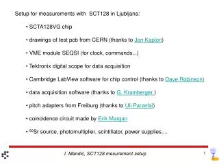
Setup for measurements with SCT128 in Ljubljana: • SCTA128VG chip • drawings of test pcb from CERN (thanks to Jan Kaplon) • VME module SEQSI (for clock, commands...) • Tektronix digital scope for data acquisition • Cambridge LabView software for chip control (thanks to Dave Robinson) • data acquisition software (thanks to G. Kramberger ) • pitch adapters from Freiburg (thanks to Uli Parzefal) • coincidence circuit made by Erik Margan • 90Sr source, photomultiplier, scintillator, power supplies.... I. Mandić, SCT128 mesurement setup
Test PCB Detector (1.2x1.2 cm2) SCTA128VG Fanin Al detector support and heat spreader PT100 I. Mandić, SCT128 mesurement setup
Aluminium support structure • dimensions: ~ 25 cm x 20 cm x 6 cm 90Sr source is inserted into the upper collimator Test board holder Scintillator is under the lower collimator Photo Multiplier Light guide I. Mandić, SCT128 mesurement setup
Setup in the freezewr, temperature about - 20° C 90Sr source holder I. Mandić, SCT128 mesurement setup
SCTA128VG chip • 128 channels • charge sensitive front-end amplifier with about 20 ns peaking time • sampled every 25 ns (40 MHz sampling clock) • Gain = 26.5 mV/fC = 4.2 µV/el measured with calibration signals • from on-chip capacitors (~10 % accuracy) • noise with detector connected ~ 800 el Strips bonded I. Mandić, SCT128 mesurement setup
Detectors • p-type, FZ material, 300 µm thick miniature (~ 1 cm2) strip detectors • strip pitch 80 µm • n-in-p capacitively coupled • polysilicon biased, p-sprayed • designed by Liverpool produced by Micron CV measurement, contact through bias ring I. Mandić, SCT128 mesurement setup
Measurements • trigger: signals caused by electrons from 90Sr source in scintillator in coincidence • with 40 MHz clock edge • spectrum of signals from strips (pedestals and common mode variations subtracted) • fitted with convolution of Landau and Gauss functions • “Most Probable Value” of the Landau function (parameter p1 in the plot below) • returned by the fit is the measure of collected charge Bias = 350 V I. Mandić, SCT128 mesurement setup
Pulse shape • signal mean vs. trigger delay, before irradiation • Bias = 200 V I. Mandić, SCT128 mesurement setup