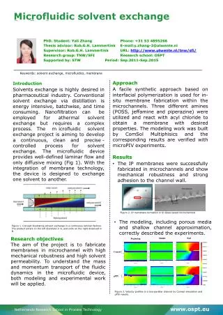
Microfluidic Chips
Microfluidic Biochips: Design, Programming, and Optimization Bill Thies Joint work with Vaishnavi Ananthanarayanan, J.P. Urbanski , Nada Amin , David Craig, Jeremy Gunawardena , Todd Thorsen , and Saman Amarasinghe Indian Statistical Institute March 2, 2011. Microfluidic Chips.

Microfluidic Chips
E N D
Presentation Transcript
Microfluidic Biochips: Design, Programming, and OptimizationBill ThiesJoint work with Vaishnavi Ananthanarayanan, J.P. Urbanski, Nada Amin, David Craig, Jeremy Gunawardena, Todd Thorsen, and Saman AmarasingheIndian Statistical InstituteMarch 2, 2011
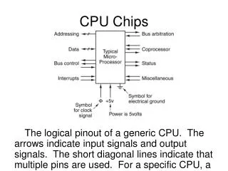
Microfluidic Chips • Idea: a whole biology lab on a single chip • Input/output • Sensors: pH, glucose, temperature, etc. • Actuators: mixing, PCR, electrophoresis, cell lysis, etc. • Benefits: • Small sample volumes • High throughput • Geometrical manipulation • Portability • Applications: • Biochemistry - Cell biology • Biological computing 10x real-time 1 mm
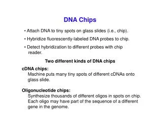
Application to Rural Diagnostics DxBox U. Washington,Micronics, Inc., Nanogen, Inc. Targets: - malaria (done) - dengue, influenza,Rickettsial diseases, typhoid, measles (under development) CARD Rheonix, Inc. Targets: - HPV diagnosis - Detection of specific gene sequences Disposable EntericCard PATH,Washington U.Micronics, Inc., U. Washington Targets: - E. coli, Shigella, Salmonella, C. jejuni
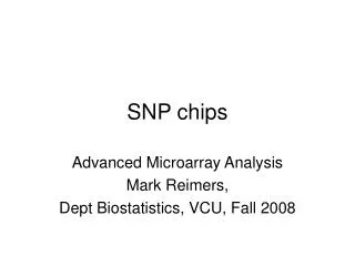
Moore’s Law of Microfluidics:Valve Density Doubles Every 4 Months Source: Fluidigm Corporation (http://www.fluidigm.com/images/mlaw_lg.jpg)
Moore’s Law of Microfluidics:Valve Density Doubles Every 4 Months Source: Fluidigm Corporation (http://www.fluidigm.com/didIFC.htm)
Current Practice: Manage Gate-Level Details from Design to Operation • For every change in the experiment or the chip design: fabricate chip 2. Operate each gate from LabView 1. Manually draw in AutoCAD
Abstraction Layers for Microfluidics Silicon Analog Protocol Description Language - architecture-independent protocol description C Fluidic Instruction Set Architecture (ISA) - primitives for I/O, storage, transport, mixing x86 Pentium III,Pentium IV chip 1 chip 2 chip 3 transistors, registers, … Fluidic Hardware Primitives - valves, multiplexers, mixers, latches
Abstraction Layers for Microfluidics Contributions Protocol Description Language - architecture-independent protocol description BioCoder Language [J.Bio.Eng. 2010] Optimized Compilation [Natural Computing 2007] Fluidic Instruction Set Architecture (ISA) - primitives for I/O, storage, transport, mixing Demonstrate Portability [DNA 2006] Micado AutoCAD Plugin [MIT 2008, ICCD 2009] chip 1 chip 2 chip 3 Digital Sample Control Using Soft Lithography [Lab on a Chip ‘06] Fluidic Hardware Primitives - valves, multiplexers, mixers, latches
Droplets vs. Continuous Flow • Digital manipulation of droplets on an electrode array [Chakrabarty, Fair, Gascoyne, Kim, …] • Pro: • Reconfigurable routing • Electrical control • More traction in CAD community Source: Chakrabarty et al, Duke University • Continuous flow of fluids (or droplets) through fixed channels [Whitesides, Quake, Thorsen, …] • Pro: • Smaller, more precise sample sizes • Made-to-order availability [Stanford] • More traction in biology community
Primitive 1: A Valve (Quake et al.) Control Layer 0. Start with mask of channels Flow Layer
Primitive 1: A Valve (Quake et al.) Control Layer 1. Deposit pattern on silicon wafer Flow Layer
Primitive 1: A Valve (Quake et al.) Control Layer 2. Pour PDMS over mold - polydimexylsiloxane: “soft lithography” Thick layer (poured) Thin layer (spin-coated) Flow Layer
Primitive 1: A Valve (Quake et al.) Control Layer 3. Bake at 80° C(primary cure), then release PDMS from mold Flow Layer
Primitive 1: A Valve (Quake et al.) Control Layer 4a. Punch hole in control channel4b. Attach flow layer to glass slide Flow Layer
Primitive 1: A Valve (Quake et al.) Control Layer 5. Align flow layer over control layer Flow Layer
Primitive 1: A Valve (Quake et al.) Control Layer 6. Bake at 80° C (secondary cure) Flow Layer
Primitive 1: A Valve (Quake et al.) 7. When pressure is high, controlchannel pinches flow channel toform a valve Control Layer pressure actuator Flow Layer
Primitive 2: A Multiplexer (Thorsen et al.) flow layer control layer Bit 2 Bit 1 Bit 0 1 1 1 0 0 0 • Control lines can cross flow lines • - Only thick parts make valves Output 7 Output 6 Output 5 Input Output 4 • Logic is not • complimentary • To control n flow lines, • need 2 log2 n control lines Output 3 Output 2 Output 1 Output 0
Primitive 2: A Multiplexer (Thorsen et al.) flow layer control layer Bit 2 Bit 1 Bit 0 1 1 1 0 0 0 • Control lines can cross flow lines • - Only thick parts make valves Output 7 Output 6 Output 5 Input Output 4 • Logic is not • complimentary • To control n flow lines, • need 2 log2 n control lines Output 3 Output 2 Output 1 Output 0 Example: select 3 = 011
Primitive 2: A Multiplexer (Thorsen et al.) flow layer control layer Bit 2 Bit 1 Bit 0 1 1 1 0 0 0 • Control lines can cross flow lines • - Only thick parts make valves Output 7 Output 6 Output 5 Input Output 4 • Logic is not • complimentary • To control n flow lines, • need 2 log2 n control lines Output 3 Output 2 Output 1 Output 0 Example: select 3 = 011
Primitive 2: A Multiplexer (Thorsen et al.) flow layer control layer Bit 2 Bit 1 Bit 0 1 1 1 0 0 0 • Control lines can cross flow lines • - Only thick parts make valves Output 7 Output 6 Output 5 Input Output 4 • Logic is not • complimentary • To control n flow lines, • need 2 log2 n control lines Output 3 Output 2 Output 1 Output 0 Example: select 3 = 011
Primitive 3: A Mixer (Quake et al.) 1. Load sample on bottom 2. Load sample on top 3. Peristaltic pumping Rotary Mixing
Primitive 4: A Latch (Our contribution) • Purpose: align sample with specific location on device • Examples: end of storage cell, end of mixer, middle of sensor • Latches are implemented as a partially closed valve • Background flow passes freely • Aqueous samples are caught Sample Latch
Primitive 4: A Latch (Our contribution) • Purpose: align sample with specific location on device • Examples: end of storage cell, end of mixer, middle of sensor • Latches are implemented as a partially closed valve • Background flow passes freely • Aqueous samples are caught Sample Latch
Primitive 5: Cell Trap • Several methods for confining cells in microfluidic chips • U-shaped weirs - C-shaped rings / microseives • Holographic optical traps - Dialectrophoresis • In our chips: U-Shaped Microseives in PDMS Chambers Source: Wang, Kim, Marquez, and Thorsen, Lab on a Chip 2007
Primitive 6: Imaging and Detection • As PDMS chips are translucent,contents can be imaged directly • Fluorescence, color, opacity, etc. • Feedback can be used todrive the experiment
Abstraction Layers for Microfluidics Protocol Description Language - architecture-independent protocol description Fluidic Instruction Set Architecture (ISA) - primitives for I/O, storage, transport, mixing chip 1 chip 2 chip 3 Fluidic Hardware Primitives - valves, multiplexers, mixers, latches
Driving Applications 1. What are the best indicators for oocyte viability? • With Mark Johnson’s andTodd Thorsen’s groups • During in-vitro fertilization, monitor cell metabolites and select healthiest embryo for implantation 2. How do mammalian signal transduction pathways respond to complex inputs? • With Jeremy Gunawardena’sand Todd Thorsen’s groups • Isolate cells and stimulate with square wave, sine wave, etc.
Driving Applications 1. What are the best indicators for oocyte viability? • With Mark Johnson’s andTodd Thorsen’s groups • During in-vitro fertilization, monitor cell metabolites and select healthiest embryo for implantation 2. How do mammalian signal transduction pathways respond to complex inputs? • With Jeremy Gunawardena’sand Todd Thorsen’s groups • Isolate cells and stimulate with square wave, sine wave, etc. Video courtesy David Craig
CAD Tools for Microfluidic Chips • Goal: automate placement, routing, control of microfluidic features • Why is this different than electronic CAD?
CAD Tools for Microfluidic Chips • Goal: automate placement, routing, control of microfluidic features • Why is this different than electronic CAD? 1. Control ports (I/O pins) are bottleneck to scalability • Pressurized control signals cannot yet be generated on-chip • Thus, each logical set of valves requires its own I/O port 2. Control signals correlated due to continuous flows Demand & opportunity for minimizing control logic pipelined flow continuous flow
Our Technique:Automatic Generation of Control Layer 1. Describe Fluidic ISA
Our Technique:Automatic Generation of Control Layer 1. Describe Fluidic ISA
Our Technique:Automatic Generation of Control Layer 1. Describe Fluidic ISA
Our Technique:Automatic Generation of Control Layer 1. Describe Fluidic ISA 2. Infer control valves
Our Technique:Automatic Generation of Control Layer 1. Describe Fluidic ISA 2. Infer control valves
Our Technique:Automatic Generation of Control Layer 1. Describe Fluidic ISA 2. Infer control valves 3. Infer control sharing
Our Technique:Automatic Generation of Control Layer 1. Describe Fluidic ISA 2. Infer control valves 3. Infer control sharing
Our Technique:Automatic Generation of Control Layer 1. Describe Fluidic ISA 2. Infer control valves 3. Infer control sharing 4. Route valves to control ports
Our Technique:Automatic Generation of Control Layer 1. Describe Fluidic ISA 2. Infer control valves 3. Infer control sharing 4. Route valves to control ports
Our Technique:Automatic Generation of Control Layer 1. Describe Fluidic ISA 2. Infer control valves 3. Infer control sharing 4. Route valves to control ports
Our Technique:Automatic Generation of Control Layer 1. Describe Fluidic ISA 2. Infer control valves 3. Infer control sharing 4. Route valves to control ports 5. Generate an interactive GUI
Our Technique:Automatic Generation of Control Layer 1. Describe Fluidic ISA 2. Infer control valves 3. Infer control sharing 4. Route valves to control ports 5. Generate an interactive GUI
Our Technique:Automatic Generation of Control Layer 1. Describe Fluidic ISA 2. Infer control valves 3. Infer control sharing 4. Route valves to control ports 5. Generate an interactive GUI
Our Technique:Automatic Generation of Control Layer 1. Describe Fluidic ISA 2. Infer control valves 3. Infer control sharing 4. Route valves to control ports 5. Generate an interactive GUI
1. Describe a Fluidic ISA • Hierarchical and composable flow declarations Sequential flow P1 P2 AND-flow F1Λ F2 OR-flow F1 \/ F2 Mixing mix(F) Pumped flow pump(F) P1 P2 F1 F2 F1 F1 or F2 F2 F F
1. Describe a Fluidic ISA mix-and-store (S1, S2, D) { 1. in1 top out 2. in2 bot out 3. mix(top bot-left bot-right top) 4. wash bot-right top bot-left store } 50x real-time