Download
1 / 18
180 likes | 347 Views
Setting Fire to CIS - or- Small Scale Combustion Chamber and Instrumentation. Dave Pogorzala Bob Kremens, PhD, Advisor Center For Imaging Science Rochester Institute of Technology 05.10.02. overview:. history project goals research methods results conclusions / future work.

E N D
SettingFireto CIS- or- Small Scale Combustion Chamber and Instrumentation Dave Pogorzala Bob Kremens, PhD, Advisor Center For Imaging Science Rochester Institute of Technology 05.10.02
overview: • history • project goals • research methods • results • conclusions / future work
history: • the Forest Fire Imaging Experimental System (FIRES) • team traveled to the Fire Sciences Lab (FSL) in Missoula, • Montana during the summer of ’01. • there they used a large combustion chamber to image several • fires with the ASD, an IR Radiation Pyrometer, and a • visible / IR camera
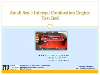
project goals: • we want to be able to image fire at any time • construct a small-scale, self standing combustion chamber • - what features from the FSL facility are needed? • allow the chamber to be tailored to other specific uses • - Adam and Jim’s project • work to be done this summer • test the chamber • - does it hold up to a full-fledged fire? • - will the instruments be able to image the fire?
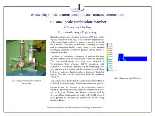
combustion chamber facility at the FSL Smoke hood Burn surface Bryce Instruments
project goals: • find fire’s emissivity • emissivity- the ratio of the radiance emitted by an object • at a certain temperature to the radiance by a perfect • blackbody at that same temperature • - “We definitely need, at a minimum, the emissivity • and temperature profiles of the flames to model a • fire with DIRSIG” • - Bob Kremens • - come to a conclusive value that could be published
research methods: chamber design • initial design was simplified • research was done on flume dynamics • no need for smoke hood and fan • - burn surface can be simulated with • an outdoor grill • - camera ports were made square • - easier to modify their size
research methods: data acquisition • both instruments had to be interfaced with the computer • developed thermocouple data logging program in VB • used preexisting program with the pyrometer thermocouplepyrometer
research methods: calculating the emissivity • the Steffan-Boltzmann Law calculated emissivity Flux (W/cm2) = e * a * T4 thermocouples pyrometer unfortunately, it was not this easy
research methods: calculating the emissivity • both instruments yielded temperature data • - thermocouples measured actual temperature of the flame • - pyrometer interpreted detected radiance as temperature • assuming an emissivity of 1.0 • emissivity was found using a look up table but it still wasn’t this easy
research methods: calculating the emissivity • the pyrometer’s rise time coefficient is < 1 sec • the thermocouple’s rise time is ~ 45sec • in order to correlate the two sets of data, a Fourier analysis • had to be done on the pyrometer data • - frequencies above 1/45 cyc/sec were removed • resulting pyrometer data was more “stable”
research methods: calculating the emissivity • temperature was read from the new pyrometer data ( ) • this was used to find the fire’s radiance; e=1.0 ( ) • this radiance was found at the fire’s actual temp ( ) • the union of the pyrometer’s radiance and the thermocouple’s • temperature yielded the emissivity ( )
results: • a set of 12 individual samples in time gave an average • emissivity of 0.265 • H. P. Telisin (1973)* measured emissivity under various • weather and fuel conditions, resulting in a range of 0.1 – 0.58
conclusions / future work: • this figure of 0.265 can be trusted, but will be verified by • additional testing this summer • add up to 5 more thermocouples to simultaneously monitor • the fire in various locations • - do temperature variations give different emissivities? • collect data on different species of wood • - different chemical compositions could yield • their own emissivities • automate the LUT process in IDL
acknowledgments: • Bob Kremens, PhD • Don Latham • Project Leader, Fire Sciences Lab, Missoula, MT • Al Simone • * Telisin, H. P. 1973, “Flame radiation as a mechanism of fire spread in forests”, • In: Heat Transfer in Flames, Vol. 2. (N.H. Afgan and J.M. Beer, eds.), 441-449. • John Wiley, New York