Download

1 / 45
500 likes | 569 Views
Explore a detailed study on combustion chamber design and cold starting procedures for direct injection diesel engines. Learn about the 'M' combustion system and its impact on engine performance.

E N D
ABSTRACT:- • In this paper, a combustion simulation model for a 4-stroke, direct injection diesel engine is described. • The combustion modeling was based on the assumption that the combustion process was taken to be only a heat addition process and the in-cylinder conditions are spatially uniform. as the heat release model, the well known wiebe’s combustion function and the white house-way’s heat release model were studied and successfully employed to the combustion simulation • A comparison has been made between the predicted results of the cylinder pressure and rate of heat release and the measured data , and showed that the predictions agreed well with the measured data.
INTRODUCTION:- • The thermodynamic cycle analysis and the performance prediction of diesel engines using the engine cycle simulation programs has become an established part of the diesel engine research and development. • Particularly ,the engine simulation programs based on the single-zone combustion model are widely used by most engine manufacturers because of simplicity and low operating cost in spite of their short comings in accuracy. • These programs can readily utilized for the prediction of cylinder firing pressure for the stress analysis of main engine parts, investigation of engine design via parameter studies
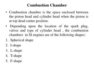
EXPERIMENTATIONS:- • This was a 4-stroke ,water-cooled , in-line 6-cylinder , direct injection and turbocharged diesel engine having ‘M’ type combustion chamber.
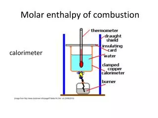
The cylinder pressure was measured by a piezo-quartz pressure transducer (AVL-8QP3000) and AVL indicating system equipped with amplifier (AVL type 3059),control unit(AVL type 3059), control unit (AVL type 4004)and 4-channel oscilloscope (Tektronix type 5103N).
‘M’ COMBUSTION SYSTEM • The ‘M’ system is a kind of direct injection combustion system . However , the ‘M’ system does not distribute the fuel in the air initially, but sprays it with a single-hole nozzle onto the oil cooled wall of the spherical combustion chamber, where it spreads to form a thin film. • The fuel is injected in the direction of a high speed air swirl which is produced during the suction stroke of the engine by the helical inlet ports. • The orientation of the fuel jet parallel with the air swirl reduces the relative velocity between the air and fuel jet which, coupled to a short distance between nozzle combustion chamber wall, helps to prevent the fuel jet being broken up to any great extent.
This means that during injection only a relatively small portion of the fuel is mixed with the air and prepared for ignition. • Therefore, independent of the temperature and stress level of the engine, there is only a very small amount of air/fuel mixtures ready for the reactions that precede combustion. • As a result, the initial rate of heat released is slowed down considerably and quiet, controlled combustion cycle achieved.
EFFECT OF PARAMETERS ON THE CYLINDER PRESSURE AND THE RATE OF HEAT RELEASE IN THE TWO WIBE FUNCTIONAL MODEL
EFFECT OF PARAMETERS ON THE CYLINDER PRSSURE AND THE RATE OF HEAT RELEASE IN THE WHITE HOUSE WAY’S MODEL
COMPARISION OF EXPERIMENTAL AND PREDICTED RESULTS FOR TEST ENGINE AT RATED SPEED AND PEAK TORQUE SPEED