Scanning Probe Microscopy Using Quartz Crystal Resonator
240 likes | 483 Views
Scanning Probe Microscopy Using Quartz Crystal Resonator. Yongho Seo Wonho Jhe School of Physics and Center for Near-field Atom-photon technology, Seoul Nation University in South Korea. QCRs as a Force Sensor. AT-cut QCR. Z-cut trident QCR. Z-cut Tuning fork. High Frequency (rf)

Scanning Probe Microscopy Using Quartz Crystal Resonator
E N D
Presentation Transcript
Scanning Probe Microscopy Using Quartz Crystal Resonator Yongho Seo Wonho Jhe School of Physics and Center for Near-field Atom-photon technology, Seoul Nation University in South Korea
QCRs as a Force Sensor AT-cut QCR Z-cut trident QCR Z-cut Tuning fork High Frequency (rf) Thickness Shear k = 105 - 106 N/m High Speed High Frequency (1 MHz) Extensional mode k = 105 - 106 N/m High resolution Low Frequency (32 kHz) Flexural Mode k = 103 - 104 N/m High force sensitivity
High Speed NSOM • Shear mode • 2 MHz dithering frequency • - make a hole to insert optical fiber tip • - easy to replace tip • - increased the stability • - high Q-value > 103
Fastest Scanning NSOM Image Topography of CD Total time : 20 s Optical image of Grating Total time : 0.5 s 7x7 mm2 Y. Seo, et. al, Appl. Phys. Lett. 77 4274 (2000).
Continuous Images usingHigh Speed Shear Force Microscope Slowly diffusing micro-spheres in water 3 min. 6 min. 9 min. 12 min 0 min. Scanning time 25 s, 5 x 4 mm2 Y. Seo and W. Jhe, Rev. Sci. Instrum. 73, 2057 (2002)
Tuning Fork Based Electrostatic force microscopy • Ferroelectrics • surface charge in Semiconductor f = 32.768 KHz k = 1300 N/m L = 2.2 mm, t = 190 mm, w = 100 mm k = 1300 N/m. Q = 1800, f = 32 kHz
Force Sensitivity of Quartz Tuning Fork minimum detectable force = (k/Qf) 1/2 Si Cantilever Quartz Tuning Fork f = 10 - 100 kHz k = 1 - 100 N/m Q = 102 - 103 ~ 10 nm dithering f = 10 - 100 kHz k = 103 - 105 N/m Q = 103 - 105 < 1 nm dithering Lift mode • Long range electrostatic force • Short range shear force • keep constant gap between tip and sample (~10 nm) • to avoid the strong short range topographic contrast
Tip Manufacture Electrochemical Etching - Co or Ni wire H3PO4 H3PO4 Pt Co, Ni D = 100 mm 10 mm
Tip Attachment -Attach the wire to the tuning fork and make a tip -Use home-made micromanipulator Pt Silver paint Co, Ni H3PO4 Tuning fork
Ferroelectric PZT Thin Film PZT (100 nm) / Pt electrode layer / Si substrate • for high quality nano storage devices : • high ferroelectric properties • long term stability and reliability
Approach Curve in EFM Tip PZT Pt Bias voltage applied between the tip and Pt substrate
Poling and Drawing by EFM polarization poling Line drawing 7 x 7 mm2 0.9 x 0.9 mm2 long time stable (10 hr) High resolution (50 nm) narrow line width
Patterning and Imaging by EFM Tuning Fork based EFM - polarization images 4 x 4 mm2 7 x 7 mm2 Y. Seo, et al, Appl. Phys. Lett. 80 4324, (2002).
Tuning Fork Based Magnetic Force Microscopy MFM contrast - magnetic force gradient between tip and sample Force gradient Frequency shift Phase shift Magnetic force - very weak force (~pN) Lift mode - keep constant gap between tip and sample (~10 nm) - to avoid the strong short range topographic contrast
Approach Curve of MFM Approach Withdraw Shear force attractive force high S/N ratio high frequency Sensitivity < 3 mHz
Tip & Tuning Fork epoxy Co or Ni tip L = 2.2 mm, t = 190 mm, w = 100 mm spring constant, k = 1300 N/m
Shear Mode MFM Advantage of the shear mode MFM • Perpendicularly • recorded sample • longitudinally • polarized tip • - monopole approximation
Magnetic Force Microscopy Images (a) shear mode, Co tip, perpendicular (b) shear mode, Co tip, parallel dithering (c) shear mode, Ni tip (d) tapping mode 100 Mbit / Inch2 hard disk 30 x 30 mm2 30 x 30 mm2 30 x 30 mm2 30 x 30 mm2
Lift Height & Dithering Amplitude Height (h) dependency Amplitude (a) dependency Tip h a Sample 3 x 1 mm2 13 x 3 mm2
High Resolution Tuning Fork Based MFM 1 Gbit/inch2 hard disk Dithering Amplitude : 20 nm lift height : 50 nm Spatial resolution : 50 nm 2 x 2 mm2
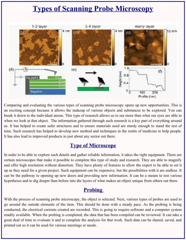
Atomic Layer of HOPG With Trident QCR (1MHz) Atomic layer (3Å) 160 x160 nm2
True Atomic resolution AFM in air • Mica • Ambient condition • Non-contact AFM • Dithering Amp: 0.1 nm • Triangular structure • k = 50,000 N/m • Trident QCR, 1MHz • Piezoelectric detection • Corrugation : 0.3 Å 1nm x 1nm, 51 s 1nm x 1nm 13 s 2nm x 2nm, 51 s 2nm x 2nm, 13 s
Summary • AT-cut QCR : High speed NSOM • Tuning fork : High force sensitivity MFM, EFM • Trident QCR : Atomic resolution AFM in air
Thank you !!! Near field Group Researchers Yongho Seo, Ho Jin Cho, Moon Hun Hong, Jun Mo An, Sung Jin Jang, Hwan Sung Choi, Kyeong Ho Kim, Professor Wonho Jhe