Download
1 / 11
250 likes | 1k Views
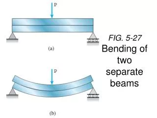
FIG. 5-27 Bending of two separate beams. Shear in beam bending. Normal Strain (tensile). Shear Strain. Deformation is a combination of normal and shear strains. FIG. 5-26 Shear stresses in a beam of rectangular cross section.

E N D
Normal Strain (tensile) Shear Strain
FIG. 5-26Shear stresses in a beam of rectangular cross section
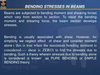
The shear stress at a distance y from the neutral axis is given by: where t V is the internal shear force I is the moment of inertia of the entire cross-section about the neutral axis Q is the first moment of the sectioned area A’ about the neutral axis For derivation see Hibbeler page 375, 376
The beam is made from two boards. What is the maximum shear stress in the glue required to hold the boards together along the seam where they are joined? Only vertical reactions occur at B&C. 1. Calculate the maximum shear stress 2. Calculate Q 3. Calculate shear stress Turn in one solution per group.
Shear Stresses In Beams Recall from the example in the last lecture that: We can find a general expression for Q
Shear Stresses In Wide Flanged I-Beams 2 Flanges + Web. The shear stress distribution is now a little more complicated. You can calculate the shear stress as a function of position using
Calculate the shear stress if a load of 7kip is applied as shown as a function of position in the beam every 0.5” between the top surface and the neutral axis. What is the maximum stress? Plot the data on the graph.