Download
1 / 18
200 likes | 1.52k Views
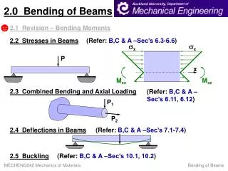
Chapter 6 Shearing Stresses in Beams and Thin-Walled Members. Introduction. Previously, for transverse loading, we limited our analysis to the normal stresses caused by bending moments since the dominant criterion in the design of a beam for strength is the maximum value of the normal stress.

E N D
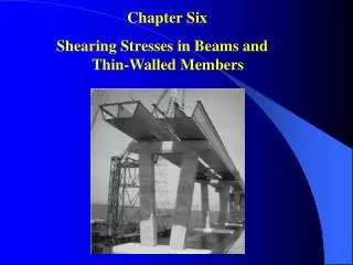
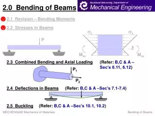
Chapter 6 Shearing Stresses in Beams and Thin-Walled Members
Introduction Previously, for transverse loading, we limited our analysis to the normal stresses caused by bending moments since the dominant criterion in the design of a beam for strength is the maximum value of the normal stress. Transverse loading will lead to shearing stresses too. For the design of beams with particular cross sections, shearing stresses can be important, and thus their analysis will be considered. In the picture, a reinforced deck will be attached to each of the steel sections shown to form a composite box girder bridge. In this part of the course, the shearing stresses will be determined in various types of beams and girders.
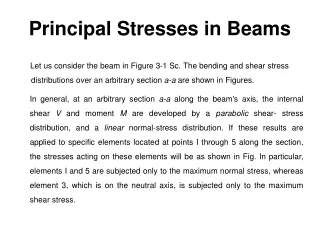
Introduction Transverse loading applied to a beam results in normal and shearing stresses in transverse sections. Distribution of normal and shearing stresses satisfies Consider the case When shearing stresses are exerted on the vertical faces of an element, equal stresses must be exerted on the horizontal faces
Introduction If τxy is present then τyxmust be present too. This means that longitudinal shearing stresses must exist in any member subjected to transverse loading. Consider a cantilever beam made of separate planks clamped together at one end. When subjected to a transverse load P, the planks are observed to slide with respect to each other. While sliding does not exist, the tendency to slide does exist, showing that stresses occur on longitudinal and transverse planes. When a moment M is applied the planks will bend into concentric arcs of circle and will not slide, thus verifying the fact that shear does not occur in a beam subjected to pure bending.
Shear on the Horizontal Face of a Beam Consider the prismatic beam shown and at a distance x from A, detach from the beam an element, CDD’C’ of length Δx. For equilibrium of beam element
Shear on the Horizontal Face of a Beam Let Q be the first moment with respect to the neutral axis of the cross section a located above the line y = y1 Let q be the shear flow, the horizontal shear per unit length
Shear on the Horizontal Face of a Beam Q: First moment above y1 I: Second moment of A Shear flow on the Upper area Shear flow on the Lower area Q’: First moment of a’ below y1 Q+Q’ : First moment of A with respect of the neutral axis
Shearing Stress in a Beam The average shearing stress on the horizontal face of the element is obtained by dividing the shearing force on the element by the area of the face. On the upper and lower surfaces of the beam, τyx= 0. It follows that τxy= 0 on the upper and lower edges of the transverse sections. If the width of the beam remains small compared to its depth, the shearing stress varies slightly along the line D1’D2’.
Shearing Stresses in Common Beams Rectangular cross section
Shearing Stresses in Common Beams American Standard (S-beam) and wide-flange (W-beam) beams Assume that the entire shear load is carried by the web
Example 1 6-1: Three full-size 50 × 100-mm boards are nailed together to form a beam that is subjected to a vertical shear of 1500 N. Knowing that the allowable shearing force in each nail is 400 N, determine the largest longitudinal spacing s that can be used between each pair of nails.
Example 2 6-10: For the beam and loading shown, consider section n-n and determine (a) the largest shearing stress in that section, (b) the shearing stress at point a.
Example 3 6-18: For the beam and loading shown, determine the minimum required width b, knowing that for the grade of timber used, σall= 12 MPa and τall = 825 kPa.
Example 4 6-21: For the beam and loading shown, consider section n-n and determine the shearing stress at (a) point a, (b) point b.