Download
1 / 22
230 likes | 269 Views
Learn the principles of analyzing and designing beams for bending, including how to determine shear forces, bending moments, and maximum normal stress. Explore sample problems and solutions to enhance your understanding.

E N D
5 Analysis and Design of Beams for Bending
Introduction Shear and Bending Moment Diagrams Sample Problem 5.1 Sample Problem 5.2 Relations Among Load, Shear, and Bending Moment Sample Problem 5.3 Sample Problem 5.5 Design of Prismatic Beams for Bending Sample Problem 5.8 Analysis and Design of Beams for Bending
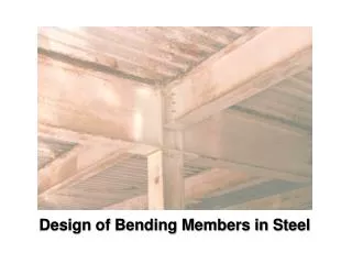
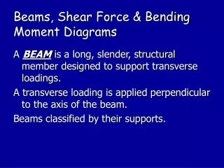
Normal stress is often the critical design criteria Requires determination of the location and magnitude of largest bending moment Introduction • Objective - Analysis and design of beams • Beams - structural members supporting loads at various points along the member • Transverse loadings of beams are classified as concentrated loads or distributed loads • Applied loads result in internal forces consisting of a shear force (from the shear stress distribution) and a bending couple (from the normal stress distribution)
Introduction Classification of Beam Supports
Sign conventions for shear forces V and V’ and bending couples M and M’ Shear and Bending Moment Diagrams • Determination of maximum normal and shearing stresses requires identification of maximum internal shear force and bending couple. • Shear force and bending couple at a point are determined by passing a section through the beam and applying an equilibrium analysis on the beam portions on either side of the section.
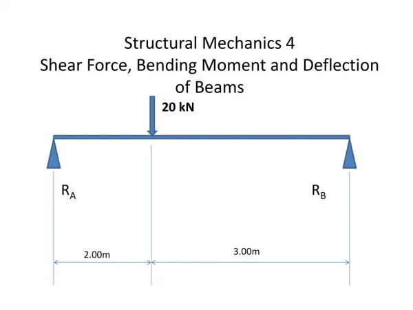
Sample Problem 5.1 • SOLUTION: • Treating the entire beam as a rigid body, determine the reaction forces • Section the beam at points near supports and load application points. Apply equilibrium analyses on resulting free-bodies to determine internal shear forces and bending couples For the timber beam and loading shown, draw the shear and bend-moment diagrams and determine the maximum normal stress due to bending. • Identify the maximum shear and bending-moment from plots of their distributions. • Apply the elastic flexure formulas to determine the corresponding maximum normal stress.
SOLUTION: • Treating the entire beam as a rigid body, determine the reaction forces • Section the beam and apply equilibrium analyses on resulting free-bodies Sample Problem 5.1
Identify the maximum shear and bending-moment from plots of their distributions. • Apply the elastic flexure formulas to determine the corresponding maximum normal stress. Sample Problem 5.1
Sample Problem 5.2 • SOLUTION: • Replace the 10 kip load with an equivalent force-couple system at D. Find the reactions at B by considering the beam as a rigid body. • Section the beam at points near the support and load application points. Apply equilibrium analyses on resulting free-bodies to determine internal shear forces and bending couples. The structure shown is constructed of a W10x112 rolled-steel beam. (a) Draw the shear and bending-moment diagrams for the beam and the given loading. (b) determine normal stress in sections just to the right and left of point D. • Apply the elastic flexure formulas to determine the maximum normal stress to the left and right of point D.
Section the beam and apply equilibrium analyses on resulting free-bodies. Sample Problem 5.2 • SOLUTION: • Replace the 10 kip load with equivalent force-couple system at D. Find reactions at B.
Sample Problem 5.2 • Apply the elastic flexure formulas to determine the maximum normal stress to the left and right of point D. From Appendix C for a W10x112 rolled steel shape, S = 126 in3 about the X-X axis.
Relationship between load and shear: • Relationship between shear and bending moment: Relations Among Load, Shear, and Bending Moment
Sample Problem 5.3 • SOLUTION: • Taking the entire beam as a free body, determine the reactions at A and D. • Apply the relationship between shear and load to develop the shear diagram. • Apply the relationship between bending moment and shear to develop the bending moment diagram. Draw the shear and bending moment diagrams for the beam and loading shown.
SOLUTION: • Taking the entire beam as a free body, determine the reactions at A and D. • Apply the relationship between shear and load to develop the shear diagram. • zero slope between concentrated loads • linear variation over uniform load segment Sample Problem 5.3
Apply the relationship between bending moment and shear to develop the bending moment diagram. Sample Problem 5.3 • bending moment at A and E is zero • bending moment variation between A, B, C and D is linear • bending moment variation between D and E is quadratic • net change in bending moment is equal to areas under shear distribution segments • total of all bending moment changes across the beam should be zero
Sample Problem 5.5 • SOLUTION: • Taking the entire beam as a free body, determine the reactions at C. • Apply the relationship between shear and load to develop the shear diagram. • Apply the relationship between bending moment and shear to develop the bending moment diagram. Draw the shear and bending moment diagrams for the beam and loading shown.
SOLUTION: • Taking the entire beam as a free body, determine the reactions at C. Results from integration of the load and shear distributions should be equivalent. • Apply the relationship between shear and load to develop the shear diagram. • No change in shear between B and C. • Compatible with free body analysis Sample Problem 5.5
Sample Problem 5.5 • Apply the relationship between bending moment and shear to develop the bending moment diagram. Results at C are compatible with free-body analysis
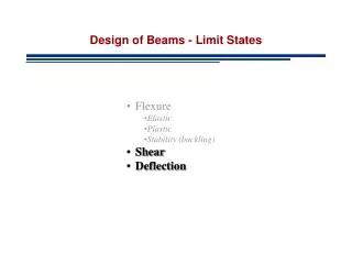
The largest normal stress is found at the surface where the maximum bending moment occurs. • A safe design requires that the maximum normal stress be less than the allowable stress for the material used. This criteria leads to the determination of the minimum acceptable section modulus. Design of Prismatic Beams for Bending • Among beam section choices which have an acceptable section modulus, the one with the smallest weight per unit length or cross sectional area will be the least expensive and the best choice.
Sample Problem 5.8 • SOLUTION: • Considering the entire beam as a free-body, determine the reactions at A and D. • Develop the shear diagram for the beam and load distribution. From the diagram, determine the maximum bending moment. A simply supported steel beam is to carry the distributed and concentrated loads shown. Knowing that the allowable normal stress for the grade of steel to be used is 160 MPa, select the wide-flange shape that should be used. • Determine the minimum acceptable beam section modulus. Choose the best standard section which meets this criteria.
Considering the entire beam as a free-body, determine the reactions at A and D. • Develop the shear diagram and determine the maximum bending moment. • Maximum bending moment occurs at V = 0 or x = 2.6 m. Sample Problem 5.8
Determine the minimum acceptable beam section modulus. • Choose the best standard section which meets this criteria. Sample Problem 5.8