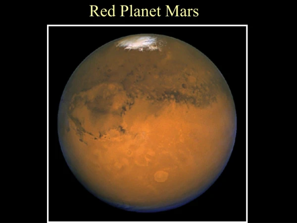
Red Planet Recycle
Chemical Engineering Design Projects 4 . Red Planet Recycle. An Investigation Into Advanced Life Support system for Mars. Tuesday 24 th January, 2 PM . Outline. Design objectives Stages 1 & 2 outline Criteria & Constraints Water treatment Air treatment Discussion. 1. Design


Red Planet Recycle
E N D
Presentation Transcript
Chemical Engineering Design Projects 4 Red Planet Recycle An Investigation Into Advanced Life Support system for Mars Tuesday 24th January, 2 PM
Outline Design objectives Stages 1 & 2 outline Criteria & Constraints Water treatment Air treatment Discussion
1. Design objectives Outline Design Brief Your consulting company has been hired by the Mars Exploration Consortium, represented by Drs.Sarkisov and Valluri. The objective of the consortium is to build a space station on Mars, capable of a continuous support of a 10 member crew.It has been planned that a re-supply mission should return to Mars every 18 months, with the main resources re-supplied being water, oxygen and food. With the current cost of the re-supplement estimated at £1 M/kg, there is a clear need for intensive onsite recycling of the resources, including water, air and waste. Your company has been hired to develop an integrated recycling solution, with an objective to minimize the weight of the re-supplement cargo.Other technologies that should be explored along with the recycling, include collection and purification of water on Mars and local production of food stock (high protein vegetables etc).The primary source of energy for the Martial station will be provided by a nuclear reactor with up to 50 MWe capacity.
1. Design objectives Outline Design Outline We have identified 3 key stages of the design: Resource requirements assuming no recycling or utilisation of local sources Resource requirements with recycling introduced Resource requirements with recycling introduced and utilisation of local resources. Investigation into unconventional technologies
1. Design objectives 2. Stages 1&2Outline Outline Stage 1 – Design basis • Using previous isolated systems as examples the essential resources that must be controlled in a life support system are: • Water • Air • Food • Waste • Thermal energy • Biomass • The last three require control but no resupply on the Mars space station, therefore these are not considered at this stage of design.
1. Design objectives 2. Stages 1&2Outline Outline Stage 1 – Resource requirements
1. Design objectives 2. Stages 1&2Outline Outline Design Outlook
1. Design objectives 2. Stages 1&2Outline Outline Stage 2 – Design basis • Stage2: Introducing recycling processes to the Mars space station in order to minimise the resupply requirements • Of the three focus resources identified in stage one, only two can effectively be recycled. These are: • Water • Air
1. Design objectives 2. Stages 1&2Outline Outline Water Recycling Assumptions: All consumed water requires recycling Assuming NASA standard water composition
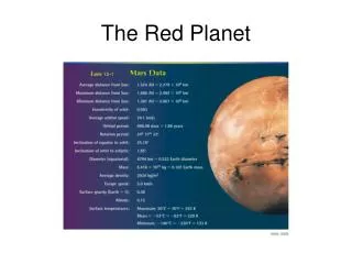
1. Design objectives 2. Stages 1&2Outline Outline Water Recycling Design Basis Stage 1 Water Waste water (ppm) Treated water (ppm) Ammonia 55 calcium 0.9 chlorine 229 phosphate 134 sulphate80 Nitrate <100 sodium 150 potassium 133 magnesium 1.5 TOC >11 Ammonia 0.05 calcium 30 chlorine 200 phosphate N/A sulphate250 Nitrate 10 sodium N/A potassium 340 magnesium 50 TOC <0.5 Flowrate 200.6 kg/day M.Flynn (1998)
1. Design objectives 2. Stages 1&2Outline Outline ? Air Recycling Assumptions: The air treatment is split into three distinct processes: CO2 separation, CO2 consumption and O2 production Assuming same composition of air as on Earth Assume N2 is a buffer
1. Design objectives 2. Stages 1&2Outline Outline ? Air Recycling Design Basis Stage 1 Air Stage 1 Air 10 kg/day CO2 Air Pre-treatment Air treatment 8.4 kg/day O2 Air
1. Design objectives 2. Stages 1&2Outline 3. Criteria & Constraints Outline Criteria & Constraints Applicability Reliability Modularity Resupply But in general we look for the technology to be; Lightweight and economical, able to recover a high percentage of waste water and operate with minimal consumables
1. Design objectives 2. Stages 1&2Outline 2. Criteria & constraints 3. Criteria & Constraints 4. Water treatment Outline ? Criteria & Constraints- Water treatment
1. Design objectives 2. Stages 1&2Outline 3. Criteria & Constraints 4. Water treatment Outline ? Criteria & Constraints- Water treatments
1. Design objectives 2. Criteria & constraints 3. Stages 1&2Outline 4. Water treatment Outline ? Water treatment- Final 5
1. Design objectives 2. Criteria & constraints 3. Stages 1&2Outline 4. Water treatment Outline ? Water treatment- Final 5
1. Design objectives 2. Criteria & constraints 3. Stages 1&2Outline 4. Water treatment Outline ? DOC VS ISS WATER RECOVERY SYSTEM • DOC requires a Re-supply of 4393 kg every 18 months • ISS Water Recovery System requires a Re-supply of 1032 kg every 18 months • Due to the difference in weight per Re-supply mission we have decided to choose to design the ISS Water Recovery System. However this is based on the 2007 paper where the recovery rate of the DOC system was 96%. If a more recent paper is able to determine a greater recovery rate the DOC system should be reconsidered for design.
1. Design objectives 2. Criteria & constraints 3. Stages 1&2Outline 4. Water treatment Outline ? Gas/Liquid Separator • The PFD shows that the stream exiting the Reactor enters the Gas/Liquid Separator before moving on to the Ion-Exchange bed. • The Stream Leaving the Reactor contains oxidized organics which need to be removed from the system. • The Separator needs to be designed to remove the excess Oxygen before the Stream continues to the IX Bed. • Excess Oxygen can be damaging and so its removal is also important for protecting expensive equipment.
1. Design objectives 2. Criteria & constraints 3. Stages 1&2Outline 4. Water treatment Outline ? Methods of Removal • In order to determine the Method of Removal the phase and composition of the stream exiting the Reactor needs to be determined • From the PFD it is known excess oxygen needs to be removed. If the oxygen is dissolved in a liquid stream, membrane degasification is an option as it is able to remove the dissolved gas by allowing it to pass through the Gas-Liquid Separation membrane.
1. Design objectives 2. Criteria & constraints 3. Stages 1&2Outline 4. Water treatment Outline ? Schematic of ISS Technology
1. Design objectives 2. Criteria & constraints 3. Stages 1&2Outline 4. Water treatment Outline ? ISS Urine Purification
1. Design objectives 2. Criteria & constraints 3. Stages 1&2Outline 4. Water treatment Outline ? List of Assumptions • The Water Safety factor of 27454.3 kg is taken up but kept in storage rather than used and put through recycling process. • It is assumed that all water used is 100% conserved and there is no loss as all vapours end up contributing to the cabin humidity which is condensed before going through the recycling process. • The required amount of water per day for the crew will be used up per day, thus the water is recycled on a daily basis. • How is water consumed on board?
1. Design objectives 2. Criteria & constraints 3. Stages 1&2Outline 4. Water treatment Outline ? Multifiltration Beds • MF consists of a particulate filter upstream of six unibedsin series. Each unibed is composed of an adsorption bed (activated carbon) and ion exchange resin bed. • Particulates are removed by filtration • Suspended organics are removed by adsorption beds • Inorganic salts are removed by ion exchange resin beds. Source: Mark Kliss, NASA ARC • The MF canisters are designed for a 30 day life, and hence will be replaced on a monthly basis.
1. Design objectives 2. Criteria & constraints 3. Stages 1&2Outline 4. Water treatment Outline ? Schematic of a MF Bed
1. Design objectives 2. Criteria & constraints 3. Stages 1&2Outline 4. Water treatment Outline ? Ref. David Robert Hokanson, MICHIGAN TECHNOLOGICAL UNIVERSITY
1. Design objectives 2. Criteria & constraints 3. Stages 1&2Outline 4. Water treatment Outline ? Water Storage • The water prior to Recycling must be stored. Based on daily recycling of 200.4 kg/day the tank would need to contain that volume plus a safety factor of 10%. • Thus the Water Tank before the process must store 220.5 kg, which corresponds to a volume of approximately 220.5 Litres. This volume includes the 20 kg/ day that will come from the urea treatment process that will join the water recovery process at the start. • Post Water Treatment • At 99 % Recovery Rate the amount of water obtained is 198.5 kg/day. Including a safety factor of 10% the total tank should accommodate 218.3 kg/day, corresponding to a volume of 218.3 litres.
1. Design objectives 2. Criteria & constraints 3. Stages 1&2Outline 4. Water treatment Outline ? Alternative Rate of Recycling Storage • Hourly Basis • Twice a day
1. Design objectives 2. Criteria & constraints 3. Stages 1&2Outline 4. Water treatment Outline ? Urine Processer Storage • The Urine Tank for the Urine Processor should be collected and recycled once daily • Materials? • Does this storage provide an acceptable hold up time? • Long term storage can occur in Teflon bags • Ultimately decided water should be recycled on a daily basis.
1. Design objectives 2. Criteria & constraints 3. Stages 1&2Outline 4. Water treatment Outline ? Gas-Liquid Separator • The PFD shows that the stream exiting the Reactor enters the Gas/Liquid Separator before moving on to the Ion-Exchange bed. • The Stream Leaving the Reactor contains excess carbon dioxide and oxygen which need to be removed from the system. • The Separator needs to be designed to remove the excess Oxygen before the Stream continues to the IX Bed. • Excess Oxygen can be damaging and so its removal is also important for protecting expensive equipment
1. Design objectives 2. Criteria & constraints 3. Stages 1&2Outline 4. Water treatment Outline ? Gas-Liquid Separator • Methods of Removal • In order to determine the Method of Removal the phase and composition of the stream exiting the Reactor needs to be determined • From the PFD it is known excess oxygen needs to be removed. If the oxygen is dissolved in a liquid stream, membrane degasification is an option as it is able to remove the dissolved gas by allowing it to pass through the Gas-Liquid Separation membrane whilst containing the liquid. • If the stream contains separated gas and liquid a vertical gas-liquid separator can be used due to low holding time • The reactor by products will remain in the liquid and thus require the ion exchange bed to remove them. • If the stream is completely in gaseous form it will require a gas separator and vice versa is the stream is completely in the liquid form.
1. Design objectives 2. Criteria & constraints 3. Stages 1&2Outline 4. Water treatment Outline ? Assumptions to be Determined? • Batch process of water? I.e. wastewater collected in a tank and when a level indicator determined the correct volume of wastewater has been reached the process can begin? • What will the level indicator be? I.e. What is the decided flow-rate for the process? • This flow rate will be based on the rate at which waste water will collect? And the rate at which recovered water is needed? • If clean water from initial mission is in storage the latter will not be an issue • How will the water from the initial supply mission be stored? Teflon bags?
1. Design objectives 2. Criteria & constraints 3. Stages 1&2Outline 4. Water treatment Outline ? Schematic of Urine Processing Assembly (UPA) Ref. Development of an Advanced Recycle Filter Tank Assembly for the ISS Urine Processor Assembly
1. Design objectives 2. Criteria & constraints 3. Stages 1&2Outline 4. Water treatment Outline ? UPA System • Urine is pretreated before enters the system with sulphuric acid and Chromium Trioxide. • The total amount of urine that will be processed for a 10 man crew is 20 kg/day.
1. Design objectives 2. Criteria & constraints 3. Stages 1&2Outline 4. Water treatment Outline ? Fluid Pump Assembly • The pump assembly consists of 4 Peristaltic pumps: • 1 supplies wastewater • 2 remove excess wastewater and sends it to the recycle filter tank • 1 removes water product water from the product side of the distillation unit (DU). Motion of the peristaltic pumps Ref. Final Report on Life Testing of the Vapor Compression Distillation/Urine Processing Assembly (VCD/UPA) at the Marshall Space Flight Center (1993 to 1997)
1. Design objectives 2. Criteria & constraints 3. Stages 1&2Outline 4. Water treatment Outline ? Distillation Assembly • Incoming wastewater is spread in a thin film on the rotating drum centrifuge. • From here it is evaporated at ambient temperature and reduced pressure • Water vapour is transferred to outside the drum through a compressor, where it condenses as clean water. • Demister ensures only clean water is removed with the compressor, leaving waste water droplets behind. • Passes through 100 micron filter before going to WPA
1. Design objectives 2. Criteria & constraints 3. Stages 1&2Outline 4. Water treatment Outline ? Distillation Assembly Ref. Final Report on Life Testing of the Vapor Compression Distillation/Urine Processing Assembly (VCD/UPA) at the Marshall Space Flight Center (1993 to 1997)
1. Design objectives 2. Criteria & constraints 3. Stages 1&2Outline 4. Water treatment Outline ? Advanced Recycle Filter Tank Assembly (ARFTA) • Filters solids from the wastewater before it is recirculated through the distillation unit. • Consists of bellows to draw waste water into the tank, and force it out as a concentrate. • Then passes through a 10μ brine filter, which has an estimated life of 60 days. • This filter has a 100μ filter incase of failure of the 10μ filter.
1. Design objectives 2. Criteria & constraints 3. Stages 1&2Outline 4. Water treatment Outline ? ARFTA Brine Filter Bellows Tank Ref. Development of an Advanced Recycle Filter Tank Assembly for the ISS Urine Processor Assembly
1. Design objectives 2. Criteria & constraints 3. Stages 1&2Outline 4. Water treatment Outline ? ARFTA Unit
1. Design objectives 2. Criteria & constraints 3. Stages 1&2Outline 4. Water treatment Outline ? Purge Pump Assembly • Removes gas from the condenser side of DU when the pressure gets to high. • Similar to fluid pumps, except operate at a higher RPM therefore require a cooling jacket • Pump system compresses the non-condensable gas & water vapour to condense the water vapour.
1. Design objectives 2. Criteria & constraints 3. Stages 1&2Outline 4. Water treatment Outline ? Purge Stream Filtration • Water that leaves these pumps is filtered using 20μ filter. • Stream then passed through water separator. This sends product water to WPA, expelling any non-condensable gases to the atmosphere.
1. Design objectives 2. Criteria & constraints 3. Stages 1&2Outline 4. Water treatment Outline ? Aqueous Catalytic Oxidation Reactor • Used as an effective post-treatment technology for the removal of low molecular weight polar (but non-ionic) organics which are not removed by sorption in the multifiltration (MF) train. • Typical contaminants of this kind are ethanol, methanol, isopropanol, acetone, and urea
1. Design objectives 2. Criteria & constraints 3. Stages 1&2Outline 4. Water treatment Outline ? Aqueous Catalytic Oxidation Reactor Design: • The reactor operating pressure is determined primarily by the requirement to maintain water in the liquid phase • The ISS uses a VRA which is co-current bubble column which uses gas phase oxygen as the oxidant over a catalyst • Catalyst consists of a noble metal on an alumina substrate • For design assume plug flow reactor
1. Design objectives 2. Criteria & constraints 3. Stages 1&2Outline 4. Water treatment Outline ? Ion Exchange Bed • Removes dissolved products of oxidation exiting the reactor • Including both organic & inorganic compounds • Organic Anion exchanged bed contains a synthetic resin, often styrene based with a capacity of 10-12 kg/ft3* (*Nalco Chemical Company, 1998)
1. Design objectives 2. Criteria & constraints 3. Stages 1&2Outline 4. Water treatment Outline ? New Proposed System • Aim to remove volatile organic compounds (VOC) from the cabin air via catalytic oxidation prior to absorption in the aqueous phase • This reduces the load on the Ion exchange bed. Oxidation kinetics indicate this is more efficient. • Second, vapour compression distillation (VCD) technology processes the condensate and hygiene waste streams in addition to the urine waste stream
1. Design objectives 2. Criteria & constraints 3. Stages 1&2Outline 4. Water treatment Outline ? New Proposed System • Experimental evidence (Carter et al.,2008) shows this system can effectively reduce the Total Organic Compounds (TOC) to ‘safe levels’: TOC removal by organic reactor Carter, et al., 2008)
1. Design objectives 2. Criteria & constraints 3. Stages 1&2Outline 4. Water treatment Outline ? Questions • The composition and Phases of the Reactor Exit Steam? • Confirmation of what needs removed from the Reactor Exit Stream prior to it entering the Ion Exchange bed? • If a Gas-Liquid Separation Membrane is the most appropriate method of Removing Oxygen?
1. Design objectives 2. Criteria & constraints 3. Stages 1&2Outline 4. Water treatment Outline ? Membrane Bioreactor – Forward Osmosis • Originally eliminated due to reliability concerns over microorganisms survival. • However after conversations with the NASA team responsible for designing waste water treatment for Mars, decision was taken to reconsider. • NASA cited this technology as their current focus, moving away from DOC & ISS • Microorganisms spores were taken to low orbit earth in 1984 with 70% survival and with developments in UV radiation protection, experts believe the technology is plausible (Benardini et al., 2005) • Membrane bioreactor has the potential for excellent treatment of waste water with removal of contaminants in excess of >95 % (Atasoy et al., 2007) • However significant challenges remain and will be investigated
1. Design objectives 2. Criteria & constraints 3. Stages 1&2Outline 4. Water treatment Outline ? Membrane Bioreactor Continued Immersed membrane Aeration zone FEED Q Si Xi Q, Se, Xe Material balances of substrate: Rsu = Q(Si-Se)/Va = …? Activated sludge