Download
1 / 92
930 likes | 1.13k Views
Chemical Engineering Design Projects 4 . Red Planet Recycle. An Investigation Into Advanced Life Support system for Mars. Tuesday 24 th January, 2 PM . Outline. Design objectives Stages 1 & 2 outline Criteria & Constraints Water treatment Air treatment Discussion. 1. Design

E N D
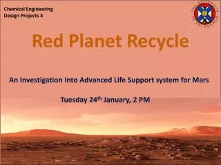
Chemical Engineering Design Projects 4 Red Planet Recycle An Investigation Into Advanced Life Support system for Mars Tuesday 24th January, 2 PM
Outline Design objectives Stages 1 & 2 outline Criteria & Constraints Water treatment Air treatment Discussion
1. Design objectives Outline Design Brief Your consulting company has been hired by the Mars Exploration Consortium, represented by Drs.Sarkisov and Valluri. The objective of the consortium is to build a space station on Mars, capable of a continuous support of a 10 member crew.It has been planned that a re-supply mission should return to Mars every 18 months, with the main resources re-supplied being water, oxygen and food. With the current cost of the re-supplement estimated at £1 M/kg, there is a clear need for intensive onsite recycling of the resources, including water, air and waste. Your company has been hired to develop an integrated recycling solution, with an objective to minimize the weight of the re-supplement cargo.Other technologies that should be explored along with the recycling, include collection and purification of water on Mars and local production of food stock (high protein vegetables etc).The primary source of energy for the Martial station will be provided by a nuclear reactor with up to 50 MWe capacity.
1. Design objectives Outline Design Outline We have identified 3 key stages of the design: Resource requirements assuming no recycling or utilisation of local sources Resource requirements with recycling introduced Resource requirements with recycling introduced and utilisation of local resources. Investigation into unconventional technologies
1. Design objectives 2. Stages 1&2Outline Outline Stage 1 – Design basis • Using previous isolated systems as examples the essential resources that must be controlled in a life support system are: • Water • Air • Food • Waste • Thermal energy • Biomass • The last three require control but no resupply on the Mars space station, therefore these are not considered at this stage of design.
1. Design objectives 2. Stages 1&2Outline Outline Stage 1 – Resource requirements
1. Design objectives 2. Stages 1&2Outline Outline Design Outlook
1. Design objectives 2. Stages 1&2Outline Outline Stage 2 – Design basis • Stage2: Introducing recycling processes to the Mars space station in order to minimise the resupply requirements • Of the three focus resources identified in stage one, only two can effectively be recycled. These are: • Water • Air
1. Design objectives 2. Stages 1&2Outline Outline Water Recycling Assumptions: All consumed water requires recycling Assuming NASA standard water composition
1. Design objectives 2. Stages 1&2Outline Outline Water Recycling Design Basis Stage 1 Water Waste water (ppm) Treated water (ppm) Ammonia 55 calcium 0.9 chlorine 229 phosphate 134 sulphate80 Nitrate <100 sodium 150 potassium 133 magnesium 1.5 TOC >11 Ammonia 0.05 calcium 30 chlorine 200 phosphate N/A sulphate250 Nitrate 10 sodium N/A potassium 340 magnesium 50 TOC <0.5 Flowrate 200.6 kg/day M.Flynn (1998)
1. Design objectives 2. Stages 1&2Outline Outline ? Air Recycling Assumptions: The air treatment is split into three distinct processes: CO2 separation, CO2 consumption and O2 production Assuming same composition of air as on Earth Assume N2 is a buffer
1. Design objectives 2. Stages 1&2Outline Outline ? Air Recycling Design Basis Stage 1 Air Stage 1 Air 10 kg/day CO2 Air Pre-treatment Air treatment 8.4 kg/day O2 Air
1. Design objectives 2. Stages 1&2Outline 3. Criteria & Constraints Outline Criteria & Constraints Applicability Reliability Modularity Resupply But in general we look for the technology to be; Lightweight and economical, able to recover a high percentage of waste water and operate with minimal consumables
1. Design objectives 2. Stages 1&2Outline 2. Criteria & constraints 3. Criteria & Constraints 4. Water treatment Outline ? Criteria & Constraints- Water treatment
1. Design objectives 2. Stages 1&2Outline 3. Criteria & Constraints 4. Water treatment Outline ? Criteria & Constraints- Water treatments
1. Design objectives 2. Criteria & constraints 3. Stages 1&2Outline 4. Water treatment Outline ? Water treatment- Final 5
1. Design objectives 2. Criteria & constraints 3. Stages 1&2Outline 4. Water treatment Outline ? Water treatment- Final 5
1. Design objectives 2. Criteria & constraints 3. Stages 1&2Outline 4. Water treatment Outline ? DOC VS ISS WATER RECOVERY SYSTEM • DOC requires a Re-supply of 4393 kg every 18 months • ISS Water Recovery System requires a Re-supply of 1032 kg every 18 months • Due to the difference in weight per Re-supply mission we have decided to choose to design the ISS Water Recovery System. However this is based on the 2007 paper where the recovery rate of the DOC system was 96%. If a more recent paper is able to determine a greater recovery rate the DOC system should be reconsidered for design.
1. Design objectives 2. Criteria & constraints 3. Stages 1&2Outline 4. Water treatment Outline ? Gas/Liquid Separator • The PFD shows that the stream exiting the Reactor enters the Gas/Liquid Separator before moving on to the Ion-Exchange bed. • The Stream Leaving the Reactor contains oxidized organics which need to be removed from the system. • The Separator needs to be designed to remove the excess Oxygen before the Stream continues to the IX Bed. • Excess Oxygen can be damaging and so its removal is also important for protecting expensive equipment.
1. Design objectives 2. Criteria & constraints 3. Stages 1&2Outline 4. Water treatment Outline ? Methods of Removal • In order to determine the Method of Removal the phase and composition of the stream exiting the Reactor needs to be determined • From the PFD it is known excess oxygen needs to be removed. If the oxygen is dissolved in a liquid stream, membrane degasification is an option as it is able to remove the dissolved gas by allowing it to pass through the Gas-Liquid Separation membrane.
1. Design objectives 2. Criteria & constraints 3. Stages 1&2Outline 4. Water treatment Outline ? Schematic of ISS Technology
1. Design objectives 2. Criteria & constraints 3. Stages 1&2Outline 4. Water treatment Outline ? ISS Urine Purification
1. Design objectives 2. Criteria & constraints 3. Stages 1&2Outline 4. Water treatment Outline ? Multifiltration Beds • MF consists of a particulate filter upstream of six unibedsin series. Each unibed is composed of an adsorption bed (activated carbon) and ion exchange resin bed. • Particulates are removed by filtration • Suspended organics are removed by adsorption beds • Inorganic salts are removed by ion exchange resin beds. Source: Mark Kliss, NASA ARC • The MF canisters are designed for a 30 day life, and hence will be replaced on a monthly basis.
1. Design objectives 2. Criteria & constraints 3. Stages 1&2Outline 4. Water treatment Outline ? Schematic of a MF Bed
1. Design objectives 2. Criteria & constraints 3. Stages 1&2Outline 4. Water treatment Outline ? Ref. David Robert Hokanson, MICHIGAN TECHNOLOGICAL UNIVERSITY
1. Design objectives 2. Criteria & constraints 3. Stages 1&2Outline 4. Water treatment Outline ? Aqueous Catalytic Oxidation Reactor • Used as an effective post-treatment technology for the removal of low molecular weight polar (but non-ionic) organics which are not removed by sorption in the multifiltration (MF) train. • Typical contaminants of this kind are ethanol, methanol, isopropanol, acetone, and urea
1. Design objectives 2. Criteria & constraints 3. Stages 1&2Outline 4. Water treatment Outline ? Aqueous Catalytic Oxidation Reactor Design: • The reactor operating pressure is determined primarily by the requirement to maintain water in the liquid phase • The ISS uses a VRA which is co-current bubble column which uses gas phase oxygen as the oxidant over a catalyst • Catalyst consists of a noble metal on an alumina substrate • For design assume plug flow reactor
1. Design objectives 2. Criteria & constraints 3. Stages 1&2Outline 4. Water treatment Outline ? Ion Exchange Bed • Removes dissolved products of oxidation exiting the reactor • Including both organic & inorganic compounds • Organic Anion exchanged bed contains a synthetic resin, often styrene based with a capacity of 10-12 kg/ft3* (*Nalco Chemical Company, 1998)
1. Design objectives 2. Criteria & constraints 3. Stages 1&2Outline 4. Water treatment Outline ? New Proposed System • Aim to remove volatile organic compounds (VOC) from the cabin air via catalytic oxidation prior to absorption in the aqueous phase • This reduces the load on the Ion exchange bed. Oxidation kinetics indicate this is more efficient. • Second, vapour compression distillation (VCD) technology processes the condensate and hygiene waste streams in addition to the urine waste stream
1. Design objectives 2. Criteria & constraints 3. Stages 1&2Outline 4. Water treatment Outline ? New Proposed System • Experimental evidence (Carter et al.,2008) shows this system can effectively reduce the Total Organic Compounds (TOC) to ‘safe levels’: TOC removal by organic reactor Carter, et al., 2008)
1. Design objectives 2. Criteria & constraints 3. Stages 1&2Outline 4. Water treatment Outline ? Questions • The composition and Phases of the Reactor Exit Steam? • Confirmation of what needs removed from the Reactor Exit Stream prior to it entering the Ion Exchange bed? • If a Gas-Liquid Separation Membrane is the most appropriate method of Removing Oxygen?
1. Design objectives 2. Criteria & constraints 3. Stages 1&2Outline 4. Water treatment 5. Air treatment Outline ? CO2 Separation CDRA - Carbon Dioxide Removal Assembly (ISS) PSA – Pressure Swing Adsorption MEA CO2Absorption Activated Carbon Absorption Scrubbers
1. Design objectives 2. Criteria & constraints 3. Stages 1&2Outline 4. Water treatment 5. Air treatment Outline ? 1. CDRA – Process Description • Utilises regenerative molecular sieve technology to remove carbon dioxide. • In the CDRA, there are four beds of two different zeolites. • Zeolite 13x absorbs water, while zeolite 5A absorbs carbon dioxide. • Each side of the CDRA contains a zeolite 13X connected to a zeolite 5A bed. • As the air passes through the zeolite 13X bed, water gets trapped and removed from the air. • The dried air goes into the zeolite 5A bed where carbon dioxide gets trapped and removed. • The outgoing air is then dry and free from carbon dioxide.
1. Design objectives 2. Criteria & constraints 3. Stages 1&2Outline 4. Water treatment 5. Air treatment Outline ? 1. CDRA – Simplified PFD
1. Design objectives 2. Criteria & constraints 3. Stages 1&2Outline 4. Water treatment 5. Air treatment Outline ? 2. PSA – Process Description • Similar process to the CDRA with the exception that pressure is used instead of heat. • Beds are operated at 150kPa or higher. • Higher the pressure, the more CO2 is adsorbed. • When bed becomes saturated it is depressurised to atmospheric levels. • CO2 is released from the bed and the regeneration is complete.
1. Design objectives 2. Criteria & constraints 3. Stages 1&2Outline 4. Water treatment 5. Air treatment Outline ? 3. MEA CO2 Absorption • This is a regenerative method of removing CO2 from air. • Uses an aqueous solution of 25-30 wt.% (4-5 M) monoethanolamine (MEA), NH2CH2CH2OH to absorb the CO2 from the air. • The aqueous solution is then regenerated by passing it through a column of packed glass rings and by heating it to drive off the CO2 under pressure. As shown below. • H-O-CH2-CH2-NH-CO-OH H-O-CH2-CH2–NH2+O=C=O
1. Design objectives 2. Criteria & constraints 3. Stages 1&2Outline 4. Water treatment 5. Air treatment Outline ? 4. Activated Carbon Adsorption • A form of carbon that has been processed to make it highly porous so as to have a very large surface area available for adsorption or chemical reactions. • CO2 saturated air is passed over the activated carbon and the CO2 is adsorbed onto the surface. • Can be regenerated by blowing air with a low CO2 concentration through the bed. • Only useful to us if we have a waste stream of air from another process that can be used to clean it. • There is no way of gaining a pure CO2 stream, which may cause problems in later processes when converting the CO2 to O2. Therefore this technology is not applicable to the space station.
1. Design objectives 2. Criteria & constraints 3. Stages 1&2Outline 4. Water treatment 5. Air treatment Outline ? 5. Scrubbers • Soda Lime – used on submarines • Constant air circulation through a scrubber system filled with 75% calcium hydroxide. CO2 is removed via the following reaction. • CO2 + Ca(OH)2 → CaCO3 + H2O • Non regenerative, Ca(OH)2 must be resupplied. • Lithium Hydroxide – used in spacesuits • Used to remove CO2 from exhaled air by one of two reactions. • 2 LiOH·H2O + CO2 → Li2CO3 + 3 H2O • 2LiOH + CO2 → Li2CO3 + H2O • Second is lighter and produces less water. • Neither systems are regenerable and LiOH must be resupplied.
1. Design objectives 2. Criteria & constraints 3. Stages 1&2Outline 4. Water treatment 5. Air treatment Outline ? Criteria & Constraints- CO2 Separation
1. Design objectives 2. Criteria & constraints 3. Stages 1&2Outline 4. Water treatment 5. Air treatment Outline ? Criteria & Constraints- CO2 Separation
1. Design objectives 2. Criteria & constraints 3. Stages 1&2Outline 4. Water treatment 5. Air treatment Outline ? CO2Separation - Final 3
1. Design objectives 2. Criteria & constraints 3. Stages 1&2Outline 4. Water treatment 5. Air treatment Outline ? CO2Separation - Final 3
1. Design objectives 2. Criteria & constraints 3. Stages 1&2Outline 4. Water treatment 5. Air treatment Outline ? CO2 Separation • Temperature swing adsorption with molecular sieves. • Temperature swing versus pressure swing. • Zeolites preferred to activated carbon for the adsorbent. • How the ISS system operates • Differences between the ISS system and that which we will design • Mass balance • Design requirements
1. Design objectives 2. Criteria & constraints 3. Stages 1&2Outline 4. Water treatment 5. Air treatment Outline ? TSA • Advantages: • Can achieve higher product purities than PSA in low CO2 environments • Cheaper than PSA • Indirect heating • Direct heating requires large volumes of adsorbent and high heating requirements. • An intercoaxial heat exchanger can solve this problem • Water circulation to provide a heat sink during adsorption • Steam condensation to provide heat for desorption
1. Design objectives 2. Criteria & constraints 3. Stages 1&2Outline 4. Water treatment 5. Air treatment Outline ? Choice of Adsorbent • Activated Carbon or Molecular Sieves? • A comparison of activated carbon to two molecular sieves (13X and 4A) showed preferential adsorption of CO2 over nitrogen or hydrogen at all pressures up to 250 psia. • 13X and 4A performed better than activated carbon at low pressures, but activated carbon was preferential at high pressures. • Our system will operate at a low (atmospheric) pressure – indicates molecular sieves are a preferential choice. • No data could be found on how activated carbon and molecular sieves act at different temperatures but all examples of TSA systems used molecular sieves – it is a proven and preferred technology.
1. Design objectives 2. Criteria & constraints 3. Stages 1&2Outline 4. Water treatment 5. Air treatment Outline ? CDRA - ISS
1. Design objectives 2. Criteria & constraints 3. Stages 1&2Outline 4. Water treatment 5. Air treatment Outline ? CDRA - ISS There are a few main differences between that system and ours that should be considered. Larger crew – capacity of system should be higher. CO2 must be recycled – on ISS the stream is vented into space and uses the vacuum outside the vessel to desorb the CO2 and vent it. An alternative system for desorption is needed.
1. Design objectives 2. Criteria & constraints 3. Stages 1&2Outline 4. Water treatment 5. Air treatment Outline ? Mass Balance 0.416667 kg/hr CO2 produced by crew members. Assuming composition of air inside the station is 20.95% O2,0.03% CO2, and the remainder (79.02%) N2. Due to the 95% CO2 removal rate 161.95 kg/hr of cabin air needs to be treated.
1. Design objectives 2. Criteria & constraints 3. Stages 1&2Outline 4. Water treatment 5. Air treatment Outline ? Mass Balance
1. Design objectives 2. Criteria & constraints 3. Stages 1&2Outline 4. Water treatment 5. Air treatment Outline ? Design Requirements 2 x Dessicant bed for water removal 2 x Adsorbent bed for CO2 adsorption Pre-cooler Vacuum system to remove the desorbed CO2 Intercoaxial HE Humidity control system (Plate heat exchanger)