Download
1 / 32
710 likes | 1.58k Views
Troubleshooting Electrical Circuits. This lesson came from Virginia Tech and has not been edited by the Georgia Curriculum Office. Notes to the Teacher.

E N D
Troubleshooting Electrical Circuits This lesson came from Virginia Tech and has not been edited by the Georgia Curriculum Office.
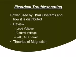
Notes to the Teacher • The content in this unit is presented with the assumption that students already know basic electrical principles and that they can wire circuits consisting of duplex receptacles and loads controlled by single-pole, three-way, and four-way switches. • This unit should take approximately 2 90-minute blocks. Note! This is an untested time-frame
Interest Approach • Bring in a bag of popcorn • Have students visualize a romantic evening with their significant other watching a movie • When they try to pop the popcorn, sparks fly out of the outlet and the appliance won’t turn back on What Happened?
Objective #1 • Given in-class instruction and laboratory application, explain electrical flow through common household/farmstead circuits with at least 70% accuracy. • State the basic components of an electrical circuit • Trace and diagram electrical flow through an unswitched circuit (duplex receptacle). • Trace and diagram electrical flow through a circuit switched by a single pole switch, by three-way switches, and by four-way switches • State whether the circuit is open or closed
What are the basic components of a switched electrical circuit? • Source • Switch • Load • Return to Source • Example #1: Light that is controlled by a single pole switch • Source? Hot wire from breaker box or previous box • Load? Light bulb • Return to Source? Neutral wire
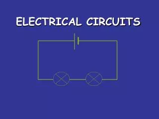
What does the switch do? Hot Wire Neutral wire Single-Pole Switch Light Is this circuit open or closed?
Example #2 • Diagram a circuit that has a duplex receptacle then 2 lights controlled by single-pole switches
Hot Wire Neutral wire Which light is on?
Three-way switched circuits • What’s the difference between a single pole switch and a three way switch? • Common terminal • How does electricity flow through it?
3-way switch Hot Wire Neutral wire Switch 1 Switch 2 Common Travelers Is this circuit open or closed?
How does a four-way work? • The four-way switch makes and X between two 3-way switches. • LOOK!! 4-way
Practice • Diagram electrical path through the following circuits 1.An open circuit consisting of a duplex receptacle and single pole switch controlling a light. 2. A closed circuit containing a light controlled by two three-way switches 3. The same circuit as Number 2 but with the electricity flowing through a different terminal 4. A closed circuit consisting of a light controlled by two three-way switches and a four-way switch.
Review • What are the basic components of an electrical circuit? Source, switch, load, return to source • Given the logic diagram on the board, identify the components represented and state whether the circuit is open or closed.
Tomorrow Now that you can visualize electrical flow through switches, you can identify and fix common problems that causes circuits to malfunction.
Objective #2 • Given laboratory demonstrations, instruction, and application identify and safely fix circuit problems with at least 70% accuracy. • Follow safety procedures • Identify and properly use receptacle testers, continuity testers, and multimeters • Use start-to-finish elimination to locate problem • Safely fix the problem
Fixing Circuit Problems • SAFETY FIRST • Process of Elimination -- Follow electricity from the source through the circuit until you find the problem. Retest circuit after making any changes • FIX THE PROBLEM
SAFETY FIRST • Turn off circuit breaker before making any repairs • Read instructions that come with circuit testing equipment. • Power be turned off when using ohmmeters and continuity testers • Have electricity on when using voltmeters
Process of Elimination • Remember that electricity has to flow from the hot wire through the load and then back to source on the neutral wire. • To find the break. Take a ride with the electricity and write down what you see.
The Road Map • Check breaker • Make sure voltage can pass through the switches • Make sure it can pass through the load to the neutral • Make sure the neutral is connected to the wiring panel
Tripped Breaker/Blown Fuse • Short Circuit – current bypassing load before returning to ground A. Identified by • smoke lined outlets and plugs • A loud “Pop” • Sparks B. Caused by • Wires touching each other • Incorrect wiring configuration
Overloaded Circuit – pulling too many amps • Identified by several appliances stopping • Caused by having too many appliances running on the same circuit. • Commonly occurs when making a big breakfast
Switches • Use a multimeter or continuity tester to make sure the switch works Multimeter Continuity Tester
Testing Switches • Make sure the breaker is off. • Turn multimeter dial to test for ohms or use a continuity tester • Attach wires to terminals and flip the switch The meter should read zero at one position and 1 at the other. The continuity tester’s light should come on at only one position • A Zero or a light indicates continuous flow • A One or no light indicates no connection
Switches cont. • Testing 3-way switches • Hook on lead to common terminal and use the other lead to check travelers • The flow should be continuous between the traveler and the common terminal depending on the position of the switch • If no continuity is found, replace the switch.
Loads • Use continuity tester to make sure the current can pass through the load • Attach one lead to the hot wire and the other to the neutral • If no connection exists, the appliance is broken.
Testing Receptacles • Use receptacle tester to make sure receptacle is wired correctly
Testing Neutral • Use continuity tester to test across any connection between the load and circuit breaker
Repairing circuit Repairs generally consist of: • Taping breaks in insulation with electrical tape • Installing new switches • Changing wiring configurations • Tightening connections • Reconnecting plug wires MAKE ALL REPAIRS WITH CIRCUIT BREAKER OFF!!!
Application • Let’s go to the shop, look at some broken circuits, and fix them. • Possible problems include: • short circuit • disconnected wires • flipped breaker • wrong wiring configuration • etc. • SAFETY FIRST AND FOLLOW TESTING EQUIPMENT INSTRUCTIONS • SEE ME BEFORE TURNING ON THE POWER
REVIEW • When a circuit doesn’t operate, where is the first place you should look? Circuit breaker • What are common signs that a short circuit has occurred? Smoke-lined outlets and plugs, sparks, loud pops • What are two things that can cause a short circuit? Wires touching each other or incorrect wiring configuration
Review cont. • What two tools are commonly used to test continuity of electrical circuits? mulitmeter(sets on ohms) and continuity tester • Should the power be turned on or off when using a continuity tester? OFF!!!! • Before making repairs, make sure the electricity is ___________________?