Download

1 / 25
250 likes | 483 Views
Electrical Circuits. How you should be thinking about electric circuits:. Voltage : a force that pushes and pulls the current through the circuit (in this picture it would be equivalent to gravity). How you should be thinking about electric circuits:.

E N D
How you should be thinking about electric circuits: Voltage: a force that pushes and pulls the current through the circuit (in this picture it would be equivalent to gravity)
How you should be thinking about electric circuits: Resistance: friction that impedes flow of current through the circuit (rocks in the river)
How you should be thinking about electric circuits: Current: the actual “substance” that is flowing through the wires of the circuit (electrons!)
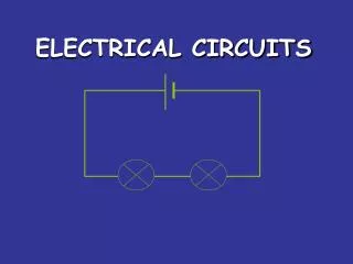
Sample Circuit: 11W 11W 12V 11W 11W 11W • Measured resistance of each light bulb to be 11 Ohms • Will apply a fixed voltage of 12V across the terminals
When I connect the 12V, which light bulb will light the brightest? Which light bulb will light the dimmest? Rate the bulbs in order from brightest to dimmest?
Let’s find out if you’re guess is correct: What is the resistance of each branch of the circuit? Branch 1 (bulbs 2 & 5): Branch 2 (bulbs 1, 3, & 4): R = 11 + 11 = 22 W R = 11 + 1/(1/11 + 1/11) = 11 + 1/(2/11) = 11 + 11/2 = 11 + 5.5 = 16.5 W
What is the current flowing through each branch of the circuit? Branch 1 (bulbs 2 & 5): Branch 2 (bulbs 1, 3, & 4): V = IR I = V/R = 12/22 = 0.54 A I = V/R = 12/16.5 = 0.73 A
Therefore, what must be the TOTAL current flowing through the circuit? I = I1 + I2 = 0.54 + 0.73 = 1.27 A However, if I actually measure the current using an Ammeter, I get… I = 0.15 A
That would mean that the light bulbs each have a resistance of: Vtot = Itot Rtot 12 = 0.15 [ 1/(1/(R branch 1) + 1/(R branch 2)) ] = 0.15 [ 1/(1/(R+R) + 1/(R + 1/(1/R + 1/R))) ] = 0.15 [ 1/(1/2R + 1/(R + 1/(2/R))) ] = 0.15 [ 1/(1/2R + 1/(R + R/2)) ] = 0.15 [ 1/(1/2R + 1/(3R/2)) ] = 0.15 [ 1/(1/2R + 2/3R)] = 0.15 [6R/7] Or, R = (12 x 7)/(0.15 x 6) = 93 W
When I measured the resistance of the light bulbs, what temperature were they at? Did the temperature of the bulbs change when I turned on the 12V power supply? Is resistance dependant on temperature?
In fact, resistance is related to temperature by the equation: • R(T) = R(T0) [1+ aDT ] • Where DT = T – T0 is the difference between two temperatures • And a is the “temperature coefficient of resistivity” and depends on the material that the light bulb filaments are made of. • All regular light bulbs have tungsten filaments, with a = 0.0045 oC-1
Can we use this information to actually calculate the temperature of the light bulbs? Recall that I measured R = 11W at room temperature and I calculated that R must be 93W when the bulbs are lit (we will assume, for simplicity, that all the bulbs are the same temperature, which is not true because they are lit at different brightnesses).
R(T) = R(T0) [ 1 + aDT] 93 = 11 [ 1 + 0.0045 (Thigh – 23)] Thigh = [ (93/11 – 1) / 0.0045 ] + 23 Thigh = 1679 oC This is the temperature of the filament, not of the glass bulb surrounding the filament!
Now that we know the correct resistance (93W) of each bulb, back to figuring out why #1 was the brightest…
What is the resistance of each branch of the circuit? Branch 1 (bulbs 2 & 5): Branch 2 (bulbs 1, 3, & 4): R = 11 + 11 = 22 W R = 93 + 93 = 186 W R = 11 + 1/(1/11 + 1/11) = 11 + 1/(2/11) = 11 + 11/2 = 11 + 5.5 = 16.5 W R = 93 + 1/(1/93 + 1/93) = 93 + 1/(2/93) = 93 + 93/2 = 93 + 46.5 = 149.5 W
What is the current flowing through each branch of the circuit? Branch 1 (bulbs 2 & 5): Branch 2 (bulbs 1, 3, & 4): V = IR I = V/R = 12/22 = 0.54 A V = IR I = V/R = 12/186 = 0.065A I = V/R = 12/16.5 = 0.73 A I = V/R = 12/139.5 = 0.086 A
Therefore, what must be the TOTAL current flowing through the circuit? I = I1 + I2 = 0.54 + 0.73 = 1.27 A I = I1 + I2 = 0.065 + 0.086 = 0.15 A However, if I actually measure the current using an Ammeter, I get… I = 0.15 A
So we know the total current, and the current flowing through each branch… Now what is the current flowing through each light bulb? #2? 0.065 A #5? 0.065 A #1? 0.086 A #3? 0.043 A #4? 0.043 A
What happens if I remove bulb #4? Is the current going through all four bulbs the same? What is it? 0.065 A Is the total current still the same? What is it? 2 x 0.065 = 0.13 A
What happens if I remove bulb #5 (after replacing bulb #4)? Why did branch 1 go out? Why didn’t branch 2 get brighter?!?! (i.e., what happened to the current that was previously going through branch 1?)
To understand the answer, you must realize that we are holding the total voltage fixed at 12V, and by taking out bulbs #2 and #5 I changed the total resistance.
So with V fixed and R being changed, I HAS to change (recall V=IR). So it does not remain 0.15 A as it has been up until now. Therefore, the current from branch 1 doesn’t need to “go” anywhere. The total current of the whole circuit has simply dropped. (By an amount exactly equal to the current that used to be in branch 1).
The End