Download
1 / 63
1.15k likes | 2.6k Views
Electrical Troubleshooting. Power used by HVAC systems and how it is distributed Review Load Voltage Control Voltage VAC, A/C Power Theories of Magnetism. Understanding Voltage. Single phase high voltage from electric utility. 115V. 115V. N. 230V. L1. L2. Theory of A/C Voltage.

E N D
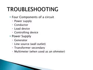
Electrical Troubleshooting Power used by HVAC systems and how it is distributed • Review • Load Voltage • Control Voltage • VAC, A/C Power • Theories of Magnetism
Understanding Voltage Single phase high voltage from electric utility 115V 115V N 230V L1 L2
Theory of A/C Voltage Single Phase 120v Sine Wave Single Phase 240v Sine Wave
Period • Positive Alternation • Negative Alternation • Amplitude
Sine Waves Out Of Phase • Phase Difference • Out of Phase • Lead • Lag
Typical Load Voltages • 120v Single Phase • Pressure • Voltmeter • 240v Single Phase • (L1) • (L2)
Common Terminology • Ground • Voltage Drop • NEC (National Electric Code • Conductor or Wire sizing • American Wire Gauge (AWG) • Circuit Protection • MCA – Minimum Circuit Ampacity • Max Fuse • Direct (dead) Short • Ground Short
Transformers • Transformer defined • Windings • Air-core transformer • Iron core transformer • Core • Primary windings • Secondary winding
Iron Core Transformers The most efficient transformer core is one that offers the best path for the most lines of flux with the least loss in magnetic and electrical energy
Basic Operation of a Transformer Primary Winding Secondary Winding
Primary and Secondary Phase Relationship The secondary voltages of a simple transformer may be either in phase or out of phase with the primary voltage
Turns and Voltage Ratios • Part A shows a transformer whose primary consists of ten turns of wire and whose secondary consists of a single turn of wire. • Turns and Current Ratios • R and C • Watts law • Amperage exercise
Transformers continued • Larger wire can carry more current without overheating • A transformer is a load, and no current will flow through the primary winding unless there is a load drawing current in the secondary side • Work through examples
Switches • Switches are needed in an electrical circuit to provide control of the loads, that is, the ability to turn them on and off when desired • Ladder diagrams • Pictorials • Symbols or Schematic
Electrical Symbols This is a partial list of most of the components you may encounter servicing HVAC equipment
Your Turn Another designation for switches is how many circuits they can switch with one or more throws. Using the symbols page, draw in these switches. S.P.S.T.– Single Pole Single Throw S.P.D.T.– Single Pole Double Throw – Sometimes called a three way switch D.P.S.T.– Double Pole Single Throw D.P.D.T.– Double Pole Double Throw – Two three way switches on one switch T.P.S.T.– Triple Pole Single Throw
Thermostats • Thermostats • Manual switches • Heat activated switches • Typically powered by 24v control voltage • Cooling anticipator • Heating Anticipator • G circuit • Examples of heating and cooling anticipators
Thermostats • Two-stage thermostat • Analog thermostat • Digital two-stage thermostat • Dead-band • Auto-changeover thermostat • Setback and Recovery thermostat • Install location
Temperature and Pressure Temperature switches are usually some form of a bi-metal device. Two metals are joined together that expand and contract at different rates causing the device to bend or warp
Temperature and Pressure • Another style is called the snap disk. These devices wait until the set temperature is reached and “snap” to the opposite position. • Auto and Manual Reset
Pressure Switch Pressure switches are similar to temperature switches in that they have specific make and break points and may use differential settings. The difference is that they are controlled by the flow/change in pressure of air, fuel, water, or refrigerant Pressure Switch Snap disk
Electrically controlled devices • These are switches that use a control voltage to change the position of a set of contacts or open and close a valve • Examples of Electrically Controlled Switches • Devices will have four ratings • Practice drawing the contact symbols for each relay
Sequencer A Sequencer has a special purpose. It is used to control multiple sets of contacts that will be closed and opened in steps instead of all at once like relays
Solenoids Solenoids are electronically controlled devices that work the same as a relay except that instead of opening or closing a set of contacts, they open or close a valve Examples: • Reversing valve • Liquid Line solenoid valves • Humidifier solenoid • Gas valves
Fan Center Fan Center is a fancy name for a transformer and fan relay mounted on a 4 x 4 cover plate that can be easily attached to a 4 x 4 gang box. There is typically a wiring diagram available on the fan center.
Loads • A load is defined as having resistance to electrical flow • Using Ohms Law, find out how the circuits on pages 51 and 52 work • Do your findings agree with the three rules of parallel circuits?
Motors, Capacitors, and Start Devices Basic components • Field coil • Stator • Armature
Motors, Capacitors, and Start Devices Induction Motors • Operating Characteristics • Types of Induction Motors • Shaded Pole • Permanent Split capacitor (PSC Motor) • Split Phase Motors
Shaded Pole • Shaded poles are characterized and named for their shaded poles (copper inserts) on each pole of the motor • These motors have only one winding • They have no capacitor • They can be single or multi-speed
Permanent Split Capacitor (PSC Motor) • The most efficient and commonly used motor in the HVAC industry • When a PSC motor is running both windings are energized. A run capacitor is wired in series with the start winding.
Pulleys A larger Drive Pulley will turn the Fan Pulley faster and vice versa. This is because the motor turns the same RPM but with a larger pulley the belt travels farther around during each revolution
Motor Ratings • LRA – Locked Rotor Amperage. • FLA/RLA – Full Load Amperage and Rated (Run) Load Amperage • CW/CCW – Clockwise and Counter Clockwise • RPM – Revolutions Per Minute • Hp – Horsepower
Sealed bearing motors • Oiling vs. Not Oiling • Frame size • Closure type
Motor Protection and Failure • All motors require some type of protection. This protection is from excessive temperatures and excessive running or starting current. AC motors used on HVAC equipment use impedance protection or thermal overloads • Impedance Protection • Thermal Overloads • Motor Failure
Capacitors • Capacitors are electrical storage devices constructed of two conducting sheets of material separated by sheets of insulating material. • Rated in Microfarads and Volts • Capacitor Safety • Capacitor Types • Capacitor Specifics
Dual Capacitors Cost-cutting measures have driven component manufacturers to incorporate two run capacitors in one container. These dual capacitors will have three terminals marked: C – Common H – Herm F – Fan
Marked Terminal Capacitors On older air conditioning products, the run capacitors were marked. These marks were used to show which terminal of the run capacitor was attached to the line side or the Run Winding Side
Capacitor Manufacturer and Symbols • Cornell Dubilier (Dash) • General Electric (Red Dot) • Mallory (Arrow) • Sprague
Series/Parallel Capacitors • Values are added together when capacitors are connected in Parallel • Capacitors wired in Series are less than the least
Testing Capacitors • Testing Oil-Filled Run Capacitors • System operating capacitor check • System off run capacitor check • Meter Specifics • Testing Start Capacitors
How Motors Really Work • PSC and Split Phase induction motors require two windings with two currents of different timing to provide starting torque for the rotor • When alternating current flows through a wire, three things occur: Resistance, Inductance, and Capacitance • Alternating Current Produces Rotating Magnetic Fields • Magnetic Rotation Starts Motors • How the Capacitor Fits In