Download

1 / 45
680 likes | 1.51k Views
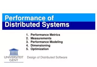
Performance Analysis of Draught Systems . P M V Subbarao Associate Professor Mechanical Engineering Department IIT Delhi. Proper combustion requires sufficient Breathing…. Draft Required to Establish Air Flow. Flue as out. Air in. Natural Draft. Z ref. p A = p ref + D p. H chimney.

E N D
Performance Analysis of Draught Systems P M V Subbarao Associate Professor Mechanical Engineering Department IIT Delhi Proper combustion requires sufficient Breathing…..
Draft Required to Establish Air Flow Flue as out Air in
Natural Draft Zref pA = pref +Dp Hchimney Tgas Tatm B A
Natural Draft • Natural Draft across the furnace, • Dpnat = pA – pB • The difference in pressure will drive the exhaust. • Natural draft establishes the furnace breathing by • Continuous exhalation of flue gas • Continuous inhalation of fresh air. • The amount of flow is limited by the strength of the draft.
Mechanical (Artificial)Draft : Induced Draft Essential when Natural Draft cannot generate required amount of breathing Hchimney pB = pfan,s pA = patm + ratm *g *Hchimney Tatm B B A Tgas
Mechanical (Artificial)Draft : Forced Draft Hchimney pB = patm + rgas *g *Hchimney pA = pfan Tgas Tatm B A
Mechanical (Artifical)Draft : Balanced Draft Hchimney pB = pfan,s pA = pfan.b B A Tatm B Tgas
+ve -ve
210 MW POWER PLANT SG Boiler drum Reheater Final Super heater Platen Super heater LTSH Economizer Coal bunker Wind Box Secondary air duct PA duct Furnace Flue gas duct APH Coal feeder F D Fan P A Fan Coal Pulverizer
Pressure drop in Air and Gas Duct Systems Bernoulli equation – pressure drop across a flow passage Frictional resistance along flow path: where f = coefficient of friction L = length of the duct, m ddl = equivalent diameter of the duct, m ρ = density of air or gas calculated at the mean gas temperature, kg/m3 u = cross section average velocity of air or gas in the duct, m/sec
Equivalent diameter for rectangular duct is given as where a and b are sides of the duct, mm. The coefficient of friction for flow through tubes can be approximated as shown below, for 5000 < Re<108, 10-6< (k/ddl)<0.01
Minor Losses Calculation of Local pressure drops: where Δp = local pressure drop K = local resistance factor, r = density of air or gas at the position of the pressure drop calculated, kg/m3 u = velocity of air through the fittings m/s.
Pressure drop across a burner pa K = 1.5 for tangential burner 3.0 for swirl burner
Pressure drop across heating surfaces S1 S2 Pressure drop across tube bundles: Inline arrangement: K = n K0 Where n = number of tube rows along the flow direction K0= loss coefficient for one row of tubes K0depends on σ1 = s1/d, σ2= s2/d , Φ = (s1- d ) Where s1is lateral pitch & s2 is longitudinal pitch If σ1<= σ2 : K0 = 1.52 (σ1 –1) – 0.5Φ –0.2Re –0.2 If σ1> σ2: K0= 0.32 (σ1 –1) – 0.5(Φ – 0.9) –0.2Re –0.2/Φ
Staggered Arrangement The loss coefficient is obtained as K = K0(n+1) Where K0is the coefficient of frictional resistance of one row of tubes K0depends on σ1 = s1/d, Φ = (s1- d ) / (s2l- d ) Where s2 lis the diagonal tube pitch given by s2 l= √ ( 0.25 s12 + s22) and K0can be written as, K0= Cs Re-0.27 Csis design parameter of the staggered banks S1 S2
For 0.17 <= Φ <= 1.7 and σ1>= 2.0, Cs= 3.2 If σ1< 2.0,then Csgiven as Cs= 3.2 + (4.6 – 2.7 Φ)(2 - σ1) For Φ = 1.7 – 5.2, Cs= 0.44(Φ+1)2
Cross-Flow over Finned Tubes • Inline arrangement • for round fins • where σ1l= (pitch of fin, Pf / diamter of tube, d) • σ2ll= (height of fin, hf / diamter of tube, d) • Re = ( u pf/ γ) • For square fine with = 0.33
1)Staggered Arrangement for round fins s1=s2=d+2hf for round fins s1=s2=2d
Pressure drop in tubular air heaters where Δpmcis the pressure drop in the tube Kin and Kout are local resistance factors at inlet and outlet Pressure drop through rotary air heater Corrugated plate-corrugated setting plate Re >= 2.8 x 10³f = 0.78 Re-0.25 Re < 2.8 x 10³f = 5.7 Re-0.5
Corrugated plate- plane setting plate Re >= 1.4 x 10³f = 0.6 Re-0.25 Re < 1.4 x 10³f = 33 Re-0.8 Plane plate- plane setting plate Re >= 1.4 x 10³f = 0. 33 Re-0.25 Re < 1.4 x 10³f = 90/ Re
Pressure drop in ducts joining air heater and dust collector The volume flow rate of gases at the induced draft fan is determined by , where Vgf= volume flow rate of gases at the exit of the duct, m3/s Tg= temperature of flue gas leaving the duct, 0C = leakage air ratio behind the air heater B = fuel firing rate, kg/s where e is the excess air ratio in the flue gas at the duct exit T0 is the cold air temperature, 0C
Pressure drop through convective section Mass conservation for unchanged density, u A = u1A1= u2 A2 local pressure loss, p1 = total loss, p = p1 + p2 + ………………….+pn= (k11 + k22 …………..+ knn) where k11= k1 (A/A1)2, k12= k2 (A/A1)2
Ash Collectors • Following Table is used to estimate the pressure drop in Ash collectors. • Cyclone: 15 – 20 m/s 70 – 90% 500 – 1000 Pa • ESP: 1– 2 m/s 99% 100 – 200 Pa
Pressure Drop through Stack where pst= stack pressure drop, Pa f = friction factor Lst= height of the chimney, m D= diamter of the chimney , m Kc= resistance factor at the stack outlet = gas density in the stack, kg/m3 uc= gas velocity at the chimney outlet, m/s
Total gas side pressure drop Pa where p1= total pressure drop from the furnace outlet to the dust collector, Pa p2= pressure drop after the dust collector, Pa = ash content in the glue gas, kg/kg pa v= average pressure of the gas, Pa pg o= flue gas density at standard conditions, kg/Nm3
The ash fraction of the flue gas calculated as, where f h= ratio of fly ash in flue gas to total ash in the fuel A = ash content of working mass, % Vg= average volume of gas from furnace to dust collector calculated from the average excess air ratio, Nm3/kg of fuel
The pressure drop from the balance point of the furnace to the chimney base is prest = pexit+ pgas –Dpnd where pexit= pressure drop up to the boiler outlet
Air Pressure Losses Total losses Dp Burner Losses APH Losses Ducts & dampers losses Percent Boiler Rating
Draught Losses Total losses Dp Furnace, SH & RH Losses Economizer Losses Ducts & dampers losses Percent Boiler Rating
Modeling of 210 MW Draught System • Pressure drop calculation in air & gas path and its comparison with design value. • Assessment of ID and FD fan power as a function of furnace pressure. • Assessment of effective kinetic rate coefficient as a function of furnace pressure. Back pass ID Fan FD Fan Duct Duct Furnace Duct APH ESP Chimney Duct APH Duct
Boiler APH ESP ID Fan Wind Box FD Fan Duct SCAPH APH Duct Pressure Variation Duct
Pressure Variation in Air & Gas Path at Part Load 2500 2000 1500 1000 500 Boiler APH ESP ID Fan Wind Box FD Fan Duct SCAPH Duct APH Duct 0 Pressure (Pa) 1 2 3 4 5 6 7 8 9 10 11 12 -500 -1000 -1500 -2000 Path Element Calculated (168 MW) Design (168 MW) Off Design Pressure Variation
Combustion and Draught Control • The control of combustion in a steam generator is extremely critical. • Maximization of operational efficiency requires accurate combustion. • Fuel consumption rate should exactly match the demand for steam. • The variation of fuel flow rate should be executed safely. • The rate of energy release should occur without any risk to the plant, personal or environment.