TRANSFORMER & REACTORS
TRANSFORMER & REACTORS. INTRODUCTION. Electricity: The clean and versatile way to provide power to the end-user . The Network It is the primary member of the electric power system. Network is always balanced Generation feeds power to the network Consumer draws power from the network .

TRANSFORMER & REACTORS
E N D
Presentation Transcript
INTRODUCTION Electricity: The clean and versatile way to provide power to the end-user The Network • It is the primary member of the electric power system. • Network is always balanced • Generation feeds power to the network • Consumer draws power from the network
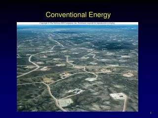
Network characteristics - AC to permit voltage transformation and current breaking - Three-phase system - Power frequency selection made once for all, 50 Hz - Generation on suitable voltage, up to 30 kV - Transmission on high voltage, increasing transmission voltage with increasing distance - Consumption at suitable voltage
The transformer • The transformer solves our problem. • It gives : Any voltage to meet all our needs
Transformers -Definition • IEC 60076-1 • A static piece of apparatus with two or more windings which, by electromagnetic induction, transforms a system of alternating voltage and current into another system of voltage and current usually of different values and at the same frequency for the purpose of transmitting electrical power. • IEEE C57.12.80-2002 • A static device consisting of a winding, or two or more coupled windings with or without a magnetic core for introducing mutual coupling between electrical circuits.
Transformer Equation • The alternating EMF applied to one of the windings establishes an alternating magnetic flux in the core, which induces an EMF in the windings. • The formula connecting induced voltage, flux and number of turns is as follows: E= 4.44 f Øm N E - RMS value of the induced emf in the winding. f - frequency of supply in Hz Øm - Total magnetic flux through the core (max.value) in Webbers. N - No. of turns in the winding.
Basic design concept • Core type Circular shaped windings • Shell type Rectangular shaped windings
Problems Associated with Reactive Power • Power transmission lines are characterized by their line inductance and shunt capacitance. • For shorter lines their inductive reactance dominates. As a result when they carry load current, which normally is inductive in nature, the receiving end voltage reduces in magnitude and hence shunt reactor are not required for such lines.
Long transmission lines present a problem of a different kind. Once energized the line charging becomes a source of reactive power. • Under light load conditions the VAR generation exceeds the VAR consumption which causes excessive voltage at mid point. • The consumed reactive power is equal to generated power for a certain transmitted load. This transmitted load is called surge impedance load of the line. • Voltage profile under this condition becomes flat. • Under heavy load condition, generation of reactive power in lines is reduced while its consumption increases substantially.
Function of Shunt Reactor: • In practice, on account of the transient stability considerations the permissible loading of long lines is kept below surge impedance loading. • Therefore one faces the challenge to restrict over voltage along the length of the line. • This is accomplished by the connection of shunt reactors. • Shunt Reactors are, thus, important components for better utilization of lines. • It compensate large capacitive currents generated by HV transmission lines over great distances.
USE OF SHUNT REACTORS • Capacitive energy is thus balanced with reactive energy. • Maintain grid voltage within limits compatible with the systems insulation level under normal service conditions. (Lightly loaded conditions) • Control over voltage under abnormal conditions (loss of system interconnections resulting from load shedding operations or from a line-ground fault. • Take care of switching transients
REACTORS - TYPE • Reactors may be • permanently connected • LINE REACTORS • switched in and off type, depending upon voltage variations • BUS REACTORS
NEUTRAL GROUNDING REACTOR (NGR) • In the transmission systems • single pole opening and re-closing of the EHV lines is used from the consideration of transient stability. • successful single pole re-closing requires that extinction of secondary arc and the deionization of arc path in faulty phase should occur before re-closing is effected.
NGR (Contd…) • To achieve this • it may be necessary to reduce secondary arc current • This requires compensation of phase to phase and phase to ground capacitance of the line. • In EHV system this is achieved by installing a single phase shunt reactor (called Neutral Grounding Reactor) between neutral point of EHV reactor and the earth.
NGR (Contd…) • The neutral earthing reactor is classified under the category of current limiting reactor. • For this reactor, no rated continuous current is applicable, unless otherwise specified. • The reactor should withstand without undue heating or excessive mechanical stresses when short time current is carried for a specified duration which is usually 1.0 sec