Download
1 / 14
150 likes | 427 Views
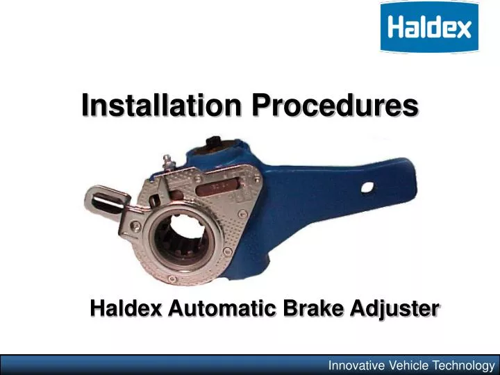
Installation Procedures. Haldex Automatic Brake Adjuster. Innovative Vehicle Technology. Why ABA’s?.

E N D
Installation Procedures Haldex Automatic Brake Adjuster Innovative Vehicle Technology
Why ABA’s? Automatic Brake Adjusters are intended to provide efficient day-to-day service braking by maintaining optimum brake chamber stroke. However, different approaches by ABA manufacturers are sometimes used in accomplishing this goal. The Haldex ABA is a “clearance sensing” brake adjuster that maintains a nominal distance or clearance between the lining and drum under a variety of braking conditions.
Trailer Applications 16 ½” Brake Assembly 12 1/4” Brake Assembly Integral cam support anchor bracket 12 ¼” & 16 ½” Brake Assemblies Bolt-on cam support anchor bracket 12 ¼” & 16 ½” Brake Assemblies
New Installation Available in 5/8” or 1 ½” Offsets • Determine what axle the adjuster will be used on. • Determine the camshaft diameter & number of splines. • Determine the adjuster arm length. • Determine if offset adjuster is required. • Select the proper ABA kit. Arm Length P/N40910224 S/N33489 Camshaft Diameter Installation Indicator
Installation Procedures Step 1 Anchor Bracket • Note: Block wheels to prevent vehicle from rolling. Ensure system tank pressure is above 100 psi. • Check that the push rod is fully retracted; apply air to release spring brake. If air is not available, spring brake must be manually caged. • Install anchor bracket loosely as illustrated (fig. 1). • Some strap brackets have two mounting holes. Proper mounting location is determined by the length of adjuster arm. 5” & 5.5” adjuster arm lengths utilize the shorter hole while 6” & 6.5” length adjusters utilize the longer hole. • Do not tighten anchor bracket fasteners at this time. • Apply anti-seize type lubricant to camshaft splines. Fig. 1 Note: Configuration of anchor bracket & brake adjuster housing may vary, depending upon axle.
Installation Procedures Step 2 • Install the brake adjuster onto the camshaft with the adjusting hex pointing away from the brake chamber (fig. 2). • Secure the brake adjuster on the camshaft. Use at least one inner washer & enough outer washers to allow no more than .060” movement of adjuster on camshaft. (Per TMC recommended practice RP609-A). • DO NOT pull push rod out to meet the brake adjuster. • Rotate the 7/16” adjusting hex nut CLOCKWISE until the clevis hole lines up with the brake adjuster arm hole. • Apply anti-seize type lubricant to clevis pin, install & secure with cotter pin. Fig. 2
Installation Procedures Step 3 Fig. 3 • Rotate the control arm away from the adjusting hex toward the air chamber, until it comes to a definite internal stop (fig. 3). • Most adjusters will be equipped with an installation indicator. The indicator must fall within the slot for proper installation with brakes fully released (fig. 4). If the control arm position is wrong, tight brakes will occur (fig. 5). • Tighten all anchor bracket fasteners (make sure the control arm does not move from its position while tightening fasteners). Fig. 5 Fig. 4 Correct (Brakes Released) Incorrect (Brakes Released)
Installation Procedures Step 4 • The adjuster must be manually adjusted at this time. • Rotate the adjusting hex clockwise until the lining contacts the drum. • Back-off the adjuster by turning the adjusting hex counter-clockwise ½ turn (fig. 6). • A minimum of 13 ft. lbs. is necessary to overcome the internal clutch. A ratcheting sound will be present. • Do NOT use an impact wrench or internal damage will occur! Fig. 6 A mis-set control arm can cause a tight brake! FINAL INSPECTION: Make sure brakes are still fully released, & check that the installation indicator is within the slotted area. If out of position, repeat Step 3.
Torque Specifications • Round anchor stud pin with fabricated ring clamp.15-20 ft. lbs. • Flat anchor stud pin. 40-50 ft. lbs. • U-Bolt style bracket. 20-30 ft. lbs. • Round anchor stud pin with slide nut. 15-20 ft. lbs. • Strap style bracket. 8-12 ft. lbs. Pic. #1 Pic. #2 Pic. #4 Pic. #3 Pic. #5
Type Adjustment Limit Type Adjustment Limit 9 1.375” 16L 2” 12 1.375” 20L 2” 16 1.750” 24L (early Design) 2” 20 1.750” 24L (Late Design) 2.50” 30L 2.50” 24 1.750” 30 2” 36 2.250” Operational Check North American Commercial Vehicle Safety Alliance StandardClamp Type Brake Chamber Long StrokeBrake Chamber *The applied stroke of the brake should be checked per CVSA guidelines at 90-100 psi reservoir pressure.
OperationalCheck New brake assemblies require a burnish period. During this time you may experience a longer stroke than normal. Vehicle must be operated and brake assemblies allowed to reach normal operating temperatures in order to achieve full burnish.
Operational Check Measuring Free Stroke If the ABA is determined to be faulty, it should be replaced immediately. Do not operate as a manual brake adjuster. Free stroke is the amount of movement of the adjuster arm required to move the brake shoes against the drum. With brakes released, measure from the face of the chamber to the center of the clevis pin “A” (fig. 19). Use a lever to move the adjuster until the shoes contact the drum “B” (fig. 19). The difference between the fully retracted & drum contact measurement “B” – “A” (fig. 19), is the free stroke. The free stroke should fall between 3/8” & 3/4”. If the free stroke is good, but the applied stroke is too long, there is likely a problem within the foundation brake system.
Adjuster Type Manufacture Date Lubrication Interval Type of Lubricant Standard Adjuster Prior to 6/1/96 50,000miles or every 3 months Standard Chassis Grease Reduced Maintenance Adjuster After 6/1/96 Once a year Standard Chassis Grease No-Lube Adjuster After 6/1/96 None *Sealed Unit Service Intervals Moly-disulfide and teflon grease should not be used in Haldex ABA’s
Innovative Vehicle Technology Thank You