Download
1 / 50
510 likes | 1.12k Views
Models of Computation. Slides Adapted From Vahid and Ptolemy Project. Design. An idea … build something that performs a certain function It is not a one step process Never done directly!!! Incremental Refinement All aspects are not considered at the beginning of the development

E N D
Models of Computation Slides Adapted From Vahid and Ptolemy Project
Design • An idea … • build something that performs a certain function • It is not a one step process • Never done directly!!! • Incremental Refinement • All aspects are not considered at the beginning of the development • Explore different possible implementations in order to maximize (or minimize) a cost function • Models can be used to reason about the properties of an object
Model -- Formalization • Model of a design with precise unambiguous semantics: • Implicit or explicit relations • inputs, outputs and (possibly) state variables • Properties • “Cost” functions • Constraints Formalization of Design + Environment =closed system of equations and inequalities over some algebra
Model of Computation • A mathematical description that has a syntax and rules for computation of the behavior described by the syntax (semantics • Used to specify the semantics of computation and concurrency • MOC allows • To capture unambiguously the required functionality • To verify correctness of the functional specification wrt properties • To synthesize part of the specification • To use different tools (all must “understand” the model) • MOC needs to • Be powerful enough for application domain • Have appropriate synthesis and validation algorithms
Models of Computation • FSMs • Discrete Event Systems • CFSMs • Data Flow Models • Petri Nets • The Tagged Signal Model • Synchronous Languages and De-synchronization • Heterogeneous Composition: Hybrid Systems and Languages • Interface Synthesis and Verification • Trace Algebra, Trace Structure Algebra and Agent Algebra Each of these provides a formal framework for reasoning about certain aspects of embedded systems.
Introduction • Describing embedded system’s processing behavior • Can be extremely difficult • Complexity increasing with increasing IC capacity • Past: washing machines, small games, etc. • Hundreds of lines of code • Today: TV set-top boxes, Cell phone, etc. • Hundreds of thousands of lines of code • Desired behavior often not fully understood in beginning • Many implementation bugs due to description mistakes/omissions • English (or other natural language) common starting point • Precise description difficult to impossible • Example: Motor Vehicle Code – thousands of pages long...
An example of trying to be precise in English • California Vehicle Code • Right-of-way of crosswalks • 21950. (a) The driver of a vehicle shall yield the right-of-way to a pedestrian crossing the roadway within any marked crosswalk or within any unmarked crosswalk at an intersection, except as otherwise provided in this chapter. • (b) The provisions of this section shall not relieve a pedestrian from the duty of using due care for his or her safety. No pedestrian shall suddenly leave a curb or other place of safety and walk or run into the path of a vehicle which is so close as to constitute an immediate hazard. No pedestrian shall unnecessarily stop or delay traffic while in a marked or unmarked crosswalk. • (c) The provisions of subdivision (b) shall not relieve a driver of a vehicle from the duty of exercising due care for the safety of any pedestrian within any marked crosswalk or within any unmarked crosswalk at an intersection. • All that just for crossing the street (and there’s much more)!
Models and languages • How can we (precisely) capture behavior? • We may think of languages (C, C++), but computation model is the key • Common computation models: • Sequential program model • Statements, rules for composing statements, semantics for executing them • Communicating process model • Multiple sequential programs running concurrently • State machine model • For control dominated systems, monitors control inputs, sets control outputs • Dataflow model • For data dominated systems, transforms input data streams into output streams • Object-oriented model • For breaking complex software into simpler, well-defined pieces
Model Classification • Criteria: Abstraction Level: Time • Untimed Model of Computation • Data does not carry timing information • Only ordering of signal is expressed • SDF, Process networks (Kahn, Dataflow) • Synchronous Model of Computation • Synchronous/reactive model • Statechart • Timed Model of Computation • Discrete-event model • Continuous time model
Poetry Recipe Story State machine Sequent. program Data- flow Models Languages English Spanish Japanese C C++ Java Recipes vs. English Sequential programs vs. C Models vs. languages • Computation models describe system behavior • Conceptual notion, e.g., recipe, sequential program • Languages capture models • Concrete form, e.g., English, C • Variety of languages can capture one model • E.g., sequential program model C,C++, Java • One language can capture variety of models • E.g., C++ → sequential program model, object-oriented model, state machine model • Certain languages better at capturing certain computation models
Text versus Graphics • Models versus languages not to be confused with text versus graphics • Text and graphics are just two types of languages • Text: letters, numbers • Graphics: circles, arrows (plus some letters, numbers) X = 1 X = 1; Y = X + 1; Y = X + 1
Partial English description System interface “Move the elevator either up or down to reach the requested floor. Once at the requested floor, open the door for at least 10 seconds, and keep it open until the requested floor changes. Ensure the door is never open while moving. Don’t change directions unless there are no higher requests when moving up or no lower requests when moving down…” up Unit Control down open floor req Request Resolver buttons inside elevator b1 b2 ... bN up1 up/down buttons on each floor up2 dn2 up3 dn3 ... dnN Introductory example: An elevator controller • Simple elevator controller • Request Resolver resolves various floor requests into single requested floor • Unit Control moves elevator to this requested floor • Try capturing in C...
Partial English description System interface “Move the elevator either up or down to reach the requested floor. Once at the requested floor, open the door for at least 10 seconds, and keep it open until the requested floor changes. Ensure the door is never open while moving. Don’t change directions unless there are no higher requests when moving up or no lower requests when moving down…” up Unit Control down open floor Sequential program model req Request Resolver Inputs: int floor; bit b1..bN; up1..upN-1; dn2..dnN; Outputs: bit up, down, open; Global variables: int req; buttons inside elevator b1 b2 ... void UnitControl() { up = down = 0; open = 1; while (1) { while (req == floor); open = 0; if (req > floor) { up = 1;} else {down = 1;} while (req != floor); up = down = 0; open = 1; delay(10); } } void RequestResolver() { while (1) ... req = ... ... } bN up1 up/down buttons on each floor up2 dn2 up3 dn3 void main() { Call concurrently: UnitControl() and RequestResolver() } ... dnN Elevator controller using a sequential program model You might have come up with something having even more if statements.
Finite-state machine (FSM) model • Trying to capture this behavior as sequential program is a bit awkward • Instead, we might consider an FSM model, describing the system as: • Possible states • E.g., Idle, GoingUp, GoingDn, DoorOpen • Possible transitions from one state to another based on input • E.g., req > floor • Actions that occur in each state • E.g., In the GoingUp state, u,d,o,t = 1,0,0,0 (up = 1, down, open, and timer_start = 0) • Try it...
req > floor u,d,o, t = 1,0,0,0 GoingUp !(req > floor) timer < 10 req > floor !(timer < 10) u,d,o,t = 0,0,1,0 UnitControl process using a state machine Idle DoorOpen u,d,o,t = 0,0,1,1 req == floor req < floor !(req<floor) u,d,o,t = 0,1,0,0 GoingDn u is up, d is down, o is open req < floor t is timer_start Finite-state machine (FSM) model
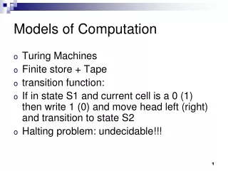
Formal definition • An FSM is a 6-tuple F<S, I, O, F, H, s0> • S is a set of all states {s0, s1, …, sl} • I is a set of inputs {i0, i1, …, im} • O is a set of outputs {o0, o1, …, on} • F is a next-state function (S x I→ S) • H is an output function (S → O) • s0is an initial state • Moore-type • Associates outputs with states (as given above, H maps S → O) • Mealy-type • Associates outputs with transitions (H maps S x I→ O) • Shorthand notations to simplify descriptions • Implicitly assign 0 to all unassigned outputs in a state • Implicitly AND every transition condition with clock edge (FSM is synchronous)
Finite-state machine with datapath model (FSMD) • FSMD extends FSM: complex data types and variables for storing data • FSMs use only Boolean data types and operations, no variables • FSMD: 7-tuple <S, I , O, V, F, H, s0> • S is a set of states {s0, s1, …, sl} • I is a set of inputs {i0, i1, …, im} • O is a set of outputs {o0, o1, …, on} • V is a set of variables {v0, v1, …, vn} • F is a next-state function (S x I x V→ S) • H is an action function (S → O + V) • s0 is an initial state • I,O,V may represent complex data types (i.e., integers, floating point, etc.) • F,H may include arithmetic operations • H is an action function, not just an output function • Describes variable updates as well as outputs • Complete system state now consists of current state, si, and values of all variables We described UnitControl as an FSMD req > floor u,d,o, t = 1,0,0,0 GoingUp !(req > floor) timer < 10 req > floor !(timer < 10) u,d,o,t = 0,0,1,0 Idle DoorOpen u,d,o,t = 0,0,1,1 req == floor req < floor !(req<floor) u,d,o,t = 0,1,0,0 GoingDn u is up, d is down, o is open req < floor t is timer_start
req > floor u,d,o, t = 1,0,0,0 GoingUp !(req > floor) timer < 10 req > floor u,d,o,t = 0,0,1,0 !(timer < 10) Idle DoorOpen u,d,o,t = 0,0,1,1 req == floor req < floor !(req<floor) u,d,o,t = 0,1,0,0 GoingDn req < floor Describing a system as a state machine 1. List all possible states • 2. Declare all variables (none in this example) • 3. For each state, list possible transitions, with conditions, to other states • 4. For each state and/or transition, list associated actions • 5. For each state, ensure exclusive and complete exiting transition conditions • No two exiting conditions can be true at same time • Otherwise nondeterministic state machine • One condition must be true at any given time • Reducing explicit transitions should be avoided when first learning u is up, d is down, o is open t is timer_start
State machine vs. sequential program model • Different thought process used with each model • State machine: • Encourages designer to think of all possible states and transitions among states based on all possible input conditions • Sequential program model: • Designed to transform data through series of instructions that may be iterated and conditionally executed • State machine description excels in many cases • More natural means of computing in those cases • Not due to graphical representation (state diagram) • Would still have same benefits if textual language used (i.e., state table) • Besides, sequential program model could use graphical representation (i.e., flowchart)
Try Capturing Other Behaviors with an FSM • E.g., Answering machine blinking light when there are messages • E.g., A simple telephone answering machine that answers after 4 rings when activated • E.g., A simple crosswalk traffic control light • Others
Capturing state machines in sequential programming language • Despite benefits of state machine model, most popular development tools use sequential programming language • C, C++, Java, Ada, VHDL, Verilog, etc. • Development tools are complex and expensive, therefore not easy to adapt or replace • Must protect investment • Two approaches to capturing state machine model with sequential programming language • Front-end tool approach • Additional tool installed to support state machine language • Graphical and/or textual state machine languages • May support graphical simulation • Automatically generate code in sequential programming language that is input to main development tool • Drawback: must support additional tool (licensing costs, upgrades, training, etc.) • Language subset approach • Most common approach...
Language subset approach • Follow rules (template) for capturing state machine constructs in equivalent sequential language constructs • Used with software (e.g.,C) and hardware languages (e.g.,VHDL) • Capturing UnitControl state machine in C • Enumerate all states (#define) • Declare state variable initialized to initial state (IDLE) • Single switch statement branches to current state’s case • Each case has actions • up, down, open, timer_start • Each case checks transition conditions to determine next state • if(…) {state = …;} #define IDLE0 #define GOINGUP1 #define GOINGDN2 #define DOOROPEN3 void UnitControl() { int state = IDLE; while (1) { switch (state) { IDLE: up=0; down=0; open=1; timer_start=0; if (req==floor) {state = IDLE;} if (req > floor) {state = GOINGUP;} if (req < floor) {state = GOINGDN;} break; GOINGUP: up=1; down=0; open=0; timer_start=0; if (req > floor) {state = GOINGUP;} if (!(req>floor)) {state = DOOROPEN;} break; GOINGDN: up=1; down=0; open=0; timer_start=0; if (req < floor) {state = GOINGDN;} if (!(req<floor)) {state = DOOROPEN;} break; DOOROPEN: up=0; down=0; open=1; timer_start=1; if (timer < 10) {state = DOOROPEN;} if (!(timer<10)){state = IDLE;} break; } } } UnitControl state machine in sequential programming language
General template #define S0 0 #define S1 1 ... #define SN N void StateMachine() { int state = S0; // or whatever is the initial state. while (1) { switch (state) { S0: // Insert S0’s actions here & Insert transitions Ti leaving S0: if( T0’s condition is true ) {state = T0’s next state; /*actions*/ } if( T1’s condition is true ) {state = T1’s next state; /*actions*/ } ... if( Tm’s condition is true ) {state = Tm’s next state; /*actions*/ } break; S1: // Insert S1’s actions here // Insert transitions Ti leaving S1 break; ... SN: // Insert SN’s actions here // Insert transitions Ti leaving SN break; } } }
StateCharts • Visual Formalism for Complex Systems • An extension of conventional FSMs • Conventional FSMs are inappropriate for the behavioral description of complex control • flat and unstructured • inherently sequential in nature • StateCharts supports repeated decomposition of states into sub-states in an AND/OR fashion, combined with a synchronous (instantaneous broadcast communication mechanism State Diagrams + Depth + Orthogonality +Broadcast
State Decomposition • OR-States have sub-states that are related to each other by exclusive-or • AND-States have orthogonal state components (synchronous FSM composition) • AND-decomposition can be carried out on any level of states (more convenient than allowing only one level of communicating FSMs) • Basic States have no sub-states (bottom of hierarchy) • Root State : no parent states (top of hierarchy)
Without hierarchy With hierarchy A1 z A w x A1 z y B x y B A2 w z A2 Concurrency B C D C1 D1 x u y v C2 D2 HCFSM and the Statecharts language • Hierarchical/concurrent state machine model (HCFSM) • Extension to state machine model to support hierarchy and concurrency • States can be decomposed into another state machine • With hierarchy has identical functionality as Without hierarchy, but has one less transition (z) • Known as OR-decomposition • States can execute concurrently • Known as AND-decomposition • Statecharts • Graphical language to capture HCFSM • timeout:transition with time limit as condition • history: remember last substate OR-decomposed state A was in before transitioning to another state B • Return to saved substate of A when returning from B instead of initial state
fire fire fire FireGoingDn u,d,o = 0,1,0 ElevatorController fire u,d,o = 0,0,1 floor==1 floor>1 FireDrOpen With hierarchy !fire fire UnitControl RequestResolver UnitControl NormalMode req>floor NormalMode u,d,o = 1,0,0 GoingUp !(req>floor) req>floor ... u,d,o = 0,0,1 u,d,o = 0,0,1 Idle DoorOpen timeout(10) req==floor !fire fire req<floor !(req>floor) u,d,o = 0,1,0 GoingDn req<floor FireMode FireMode fire FireGoingDn u,d,o = 0,1,0 !fire u,d,o = 0,0,1 floor==1 floor>1 FireDrOpen With concurrent RequestResolver fire UnitControl with FireMode • FireMode • When fire is true, move elevator to 1st floor and open door req>floor UnitControl u,d,o = 1,0,0 GoingUp !(req>floor) req>floor • w/o hierarchy: Getting messy! u,d,o = 0,0,1 timeout(10) u,d,o = 0,0,1 Idle DoorOpen req==floor • w/ hierarchy: Simple! req<floor !(req<floor) u,d,o = 0,1,0 GoingDn req<floor Without hierarchy
ElevatorController int req; UnitControl RequestResolver NormalMode up = down = 0; open = 1; while (1) { while (req == floor); open = 0; if (req > floor) { up = 1;} else {down = 1;} while (req != floor); open = 1; delay(10); } } ... req = ... ... !fire fire FireMode up = 0; down = 1; open = 0; while (floor > 1); up = 0; down = 0; open = 1; Program-state machine model (PSM): HCFSM plus sequential program model • Program-state’s actions can be FSM or sequential program • Designer can choose most appropriate • Stricter hierarchy than HCFSM used in Statecharts • transition between sibling states only, single entry • Program-state may “complete” • Reaches end of sequential program code, OR • FSM transition to special complete substate • PSM has 2 types of transitions • Transition-immediately (TI): taken regardless of source program-state • Transition-on-completion (TOC): taken only if condition is true AND source program-state is complete • SpecCharts: extension of VHDL to capture PSM model • SpecC: extension of C to capture PSM model • NormalMode and FireMode described as sequential programs • Black square originating within FireMode indicates !fire is a TOC transition • Transition from FireMode to NormalMode only after FireMode completed
State Decomposition b S b S c V a c V a e T d e T To be in state U the system must be EITHER in state S or in state T d To be in state U the system must be BOTH in state S or in state T
Role of appropriate model and language • Finding appropriate model to capture embedded system is an important step • Model shapes the way we think of the system • Originally thought of sequence of actions, wrote sequential program • First wait for requested floor to differ from target floor • Then, we close the door • Then, we move up or down to the desired floor • Then, we open the door • Then, we repeat this sequence • To create state machine, we thought in terms of states and transitions among states • When system must react to changing inputs, state machine might be best model • HCFSM described FireMode easily, clearly • Language should capture model easily • Ideally should have features that directly capture constructs of model • FireModewould be very complex in sequential program • Checks inserted throughout code • Other factors may force choice of different model • Structured techniques can be used instead • E.g., Template for state machine capture in sequential program language
Discrete Event Model • Main applications • System dynamic characteristics • Used in networks, hardware simulation • Execution order is determined by incoming events • Features • Natural for asynchronous digital hardware • Global synchronization • Timing simulation • Limitations • Expensive to implement in software • May over-specify and/or over-model systems
Simulation Policy • Event driven Simulation • Global event queue manages the outstanding events in the chronological order • How to resolve simultaneous events? • All events in a minimal time slot are regarded as simultaneous • VHDL uses the notion of delta time • Time-driven Simulation • Invoke every module every cycle • Skip execution if there is no incoming event
ConcurrentProcessExample() { x = ReadX() y = ReadY() Call concurrently: PrintHelloWorld(x) and PrintHowAreYou(y) } PrintHelloWorld(x) { while( 1 ) { print "Hello world." delay(x); } } PrintHowAreYou(x) { while( 1 ) { print "How are you?" delay(y); } } PrintHelloWorld ReadX ReadY PrintHowAreYou time Subroutine execution over time Enter X: 1 Enter Y: 2 Hello world. (Time = 1 s) Hello world. (Time = 2 s) How are you? (Time = 2 s) Hello world. (Time = 3 s) How are you? (Time = 4 s) Hello world. (Time = 4 s) ... Sample input and output Simple concurrent process example Concurrent process model • Describes functionality of system in terms of two or more concurrently executing subtasks • Many systems easier to describe with concurrent process model because inherently multitasking • E.g., simple example: • Read two numbers X and Y • Display “Hello world.” every X seconds • Display “How are you?” every Y seconds • More effort would be required with sequential program or state machine model
Z = (A + B) * (C - D) A B C D modulate convolve t1 t2 transform Z Nodes with more complex transformations A B C D + – t1 t2 * Z Nodes with arithmetic transformations Dataflow model • Derivative of concurrent process model • Nodes represent transformations • May execute concurrently • Edges represent flow of tokens (data) from one node to another • May or may not have token at any given time • When all of node’s input edges have at least one token, node may fire • When node fires, it consumes input tokens processes transformation and generates output token • Nodes may fire simultaneously • Several commercial tools support graphical languages for capture of dataflow model • Can automatically translate to concurrent process model for implementation • Each node becomes a process
Process 2 Process 1 FIFO Buffer FIFO Buffer FIFO Buffer Process 3 Dataflow Language Model • Processes communicating through FIFO buffers
DataFlow Networks • Karp computation graphs (‘66): seminal work • Kahn process networks (‘58): formal model • Dennis Data-flow networks (‘75): programming language for MIT DF machine • Recent implementations • Graphical • Ptolemy (UCB), Khoros (U. New Mexico), Grape (U. Leuven) • SPW (Cadence), COSSAP (Synopsys) • Textual • Silage (UCB, Mentor) • Lucid, Haskell
DataFlow Networks • A Data-flow network is a collection of functional nodes which are connected and communicate over unbounded FIFO queues • Nodes are commonly called actors • Perform computation • The bits of information that are communicated over the queues are commonly called tokens • communication via sequences of tokens carrying values • State implemented as self-loop • Determinacy: • Unique output sequences given unique input sequences • Sufficient condition: blocking read
DataFlow Networks • Example: FIR filter • single input sequence i(n) • single output sequence o(n) • o(n) = c1 i(n) + c2 i(n-1) i i i i i i i i i * c1 * c1 * c1 * c1 * c1 * c1 * c1 * c1 * c1 * c1 * c1 * c1 * c1 * c1 * c1 * c1 * c1 * c1 i(-1) i(-1) i(-1) i(-1) i(-1) i(-1) i(-1) i(-1) i(-1) + + + + + + + + + o o o o o o o o o
Kahn Process Networks • A process is a mapping from input sequences to output sequences • Blocking read, non-blocking write • Concurrent processes communicate only through one-way FIFO channels with unbounded capacity • Deterministic execution • Execution Policy • Demand driven execution • Minimize resource requirement • Data driven execution • Difficult to determine the queue size • Overflow or deadlock
Process Networks • Processes communicate via FIFO. • Parallel communication is organized as follows • Autonomous computing stations are connected to each other in a network by communication lines. • A station computes on data coming on its input lines to produce output on some or all of its output lines. • Assumptions • Communication lines are the only means of communication. • Communication lines transmit info within a finite time. • Restrictions • At any given time a computing station is either computing or waiting for information on one of its input lines. • Each computing station follows a sequential program.
KPN Example • From Kahn’s original 1974 paper process f(in int u, in int v, out int w) { int i; bool b = true; for (;;) { i = b ? wait(u) : wait(v); printf("%i\n", i); send(i, w); b = !b; } } u f w v Process alternately reads from u and v, prints the data value, and writes it to w. 20-10-2019 PAGE 41
Applications of Dataflow Models • Poor fit for a word processor • Data-flow models are weak on control intensive behavior • Common in signal-processing applications • Ordered streams of data • Simple map to pipelined hardware • Lab View, Simulink, System C Transactions • Buffers used for signal processing applications anyway • FIFO buffers allow for mediation of bursty flows up to capacity of the buffer • Rates must strictly agree on average • Good fit for block-diagram specifications • System Level RTL (directed links) • Linear/nonlinear control systems (Feedback Networks) • Network Computing • Common in Electrical Engineering • Value: reasoning about data rates, availability, latency and performance can be done abstractly • Used for top-level models before processes are designed • Allow reasoning about process requirements
Synchronous Dataflow [Lee 1987] Untimed Arcs: one-way first-in first-out (FIFO) queues Nodes: functional blocks Source nodes always enabled Others enabled when enoughsamples are on all inputs Node execution Consumes same fixed number of samples on each input arc Produces same fixed number of tokens on each output arc Consumed data is dequeued from arc Flow of data through graph does not depend on data values 3 2 A B 43
A B C D mA mB mC mD modulate convolve mt1 t1 t2 ct2 tt1 tt2 transform tZ Z Synchronous dataflow Synchronous dataflow • With digital signal-processors (DSPs), data flows at fixed rate • Multiple tokens consumed and produced per firing • Synchronous dataflow model takes advantage of this • Each edge labeled with number of tokens consumed/produced each firing • Can statically schedule nodes, so can easily use sequential program model • Don’t need real-time operating system and its overhead • How would you map this model to a sequential programming language? Try it... • Algorithms developed for scheduling nodes into“single-appearance” schedules • Only one statement needed to call each node’s associated procedure • Allows procedure inlining without code explosion, thus reducing overhead even more
number of tokens consumed number of firings per “iteration” number of tokens produced Synchronous Dataflow (SDF)Fixed Production/Consumption Rates • Balance equations (one for each channel): • Schedulable statically • Get a well-defined “iteration” • Decidable: • buffer memory requirements • deadlock fire A { … produce N … } fire B { … consume M … } channel N M
Static SDF scheduling • Main SDF scheduling theorem (Lee ‘86): • A connected SDF graph with n actors has a periodic schedule iff its topology matrix M has rank n-1 • If M has rank n-1 then there exists a unique smallest integer solution q to M q = 0 • Rank must be at least n-1 because we need at least n-1 edges (connected-ness), providing each a linearly independent row • Admissibility is not guaranteed, and depends on initial tokens on Cycles • Deadlock
Synchronous Dataflow (SDF) Delay of (n) samples n samples initially in FIFO queue Systems are determinate Execution in sequence or parallelhas same outcome (predictable) Systems can be statically analyzed Check for “sampling rate” consistency Determine/optimize FIFO queue sizes atcompile time Models systems with rational rate changes Periodic schedule fires A twice & B thrice, e.g. AABBB or ABABB 3 2 A B 3 (6) 2 Nodes are not multirate but graph is! 47
Using SDF • Static scheduling used for: • Behavioral simulation of DF (extremely efficient) • Code generation for DSP • HW synthesis (Cathedral by IMEC, Lager by UCB, …) • Issues in code generation • Execution speed (pipelining, vectorization) • Code size minimization • Data memory size minimization (allocation to FIFOs) • Processor or functional unit allocation
MoC in Electronic System Design • Design process at the so called Electronic System Level (ESL) • 3 Frameworks • Daedalus • SCE • SystemCoDesigner
Reading Material • Slides based on • E. A. Lee and A. Sangiovanni-Vincentelli, "A Framework for Comparing Models of Computation," IEEE TCAD, 17(12), December, 1998 • D. Harel, “Statecharts: A Visual Formalism for Complex Systems,” Science of Computer Programming, Vol. 8, pp. 231-274, 1987 • David Harel, et. al., "STATEMATE: A Working Environment for the Development of Complex Reactive Systems," IEEE TSE, 16(4), April1990 • Vahid and T. Givargis, Embedded System Design: A Unified Hardware/Software Introduction (Chapter 8) • Andreas Gerstlauer, et. al. Electronic System-Level Synthesis Methodologies , IEEE TCAD 2009