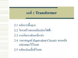
Ch.2 Transformer
the power transfer definitions and types

Ch.2 Transformer
E N D
Presentation Transcript
Ch. Two Transformer Presented by Mr. Khadar Abdi Dean of Telecommunication Eng. Electrical Eng.
Introduction • Definition of Transformer • Electrical Transformeris a static device which transforms electrical energy from one circuit to another without any direct electrical connection and with the help of mutual induction between two windings. It transforms power from one circuit to another without changing its frequency but may be in different voltage level. This is a very short and simple definition of transformer, as we will go through this portion of tutorial related to electrical power transformer, we will understand more clearly and deeply "what is transformer ?" and basic theory of transformer. Transformer
Working Principle of Transformer • The working principle of transformer is very simple. It depends upon Faraday's law of electromagnetic induction. Actually, mutual induction between two or more winding is responsible for transformation action in an electrical transformer. Faraday's Laws of Electromagnetic Induction • According to these Faraday's laws,"Rate of change of flux linkage with respect to time is directly proportional to the induced EMF in a conductor or coil". • Basic Theory of Transformer • Say you have one winding which is supplied by an alternating electrical source. The alternating current through the winding produces a continually changing flux or alternating flux that surrounds the winding. If any other winding is brought nearer to the previous one, obviously some portion of this flux will link with the second. As this flux is continually changing in its amplitude and direction, there must be a change in flux linkage in the second winding or coil. According to Faraday's law of electromagnetic induction, there must be an EMF induced in the second. If the circuit of the later winding is closed, there must be an current flowing through it. This is the simplest form of electrical power transformer and this is the most basic of working principle of transformer. Transformer
Or better understanding, we are trying to repeat the above explanation in a more brief way here. Whenever we apply alternating current to an electric coil, there will be an alternating flux surrounding that coil. Now if we bring another coil near the first one, there will be an alternating flux linkage with that second coil. As the flux is alternating, there will be obviously a rate of change in flux linkage with respect to time in the second coil. Naturally emf will be induced in it as per Faraday's law of electromagnetic induction. This is the most basic concept of the theory of transformer. • The winding which takes electrical power from the source, is generally known as primary winding of transformer. Here in our above example it is first winding. Transformer
The winding which gives the desired output voltage due to mutual induction in the transformer, is commonly known as secondary winding of transformer. Here in our example it is second winding. Transformer
The above mentioned form of transformer is theoretically possible but not practically, because in open air very tiny portion of the flux of the first winding will link with second; so the current that flows through the closed circuit of later, will be so small in amount that it will be difficult to measure. • The rate of change of flux linkage depends upon the amount of linked flux with the second winding. So, it is desired to be linked to almost all flux of primary winding to the secondary winding. This is effectively and efficiently done by placing one low reluctance path common to both of the winding. This low reluctance path is core of transformer, through which maximum number of flux produced by the primary is passed through and linked with the secondary winding. This is the most basic theory of transformer. Transformer
Main Constructional Parts of Transformer • The three main parts of a transformer are, Primary Winding of transformer- which produces magnetic flux when it is connected to electrical source. • Magnetic Core of transformer - the magnetic flux produced by the primary winding, that will pass through this low reluctance path linked with secondary winding and create a closed magnetic circuit. • Secondary Winding of transformer- the flux, produced by primary winding, passes through the core, will link with the secondary winding. This winding also wounds on the same core and gives the desired output of the transformer. Transformer
Primary winding Winding Works Transformer
Core of transformer View of Core Structure (After Completion of Core Lamination) Transformer
Symbol of Transformer Transformer
Parts of a Transformer A transformer consists of 3 basic components • Primary Coil or Primary Winding : It is an electrical wire wrapped around the core on the input side • Secondary Coil or Secondary Winding: It is an electrical wire wrapped around the core on the output side • Core : A ferromagnetic material that can conduct a magnetic field through it. Example: Iron Transformer
Transformer Structure Transformer
Transformer Operation • An electrical transformer normally consists of a ferromagnetic core and two coils called "windings". • A transformer uses the principle of mutual inductance to create an AC voltage in the secondary coil from the alternating electric current flowing through the primary coil. • The voltage induced in the secondary can be used to drive a load. Transformer
What is Mutual Inductance? • The principle of mutual inductance says that when two electrical coils are placed near to each other, AC electrical current flowing in one coilinduces an AC voltage in the other coil. • This is because current in the first coil creates a magnetic field around the first coil which in turn induces a voltage in second coil Transformer
Mutual Inductance Transformer
Transformer Operation Transformer